|
|
| Menu location |
|---|
| Modification → Edit |
| Workbenches |
| Draft |
| Default shortcut |
| D E |
| Introduced in version |
| - |
| See also |
| Std Edit |
Description
The ![]() Draft Edit command puts selected objects in Draft Edit mode. In this mode the properties of objects can be edited graphically. Typically nodes can be moved and in some cases context menu options can be selected. The command can handle most Draft objects, but also some other objects. See Supported objects. Supported Draft objects can also be put in Draft Edit mode with the Std Edit command.
Draft Edit command puts selected objects in Draft Edit mode. In this mode the properties of objects can be edited graphically. Typically nodes can be moved and in some cases context menu options can be selected. The command can handle most Draft objects, but also some other objects. See Supported objects. Supported Draft objects can also be put in Draft Edit mode with the Std Edit command.
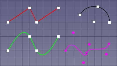
4 objects in Draft Edit mode: a Draft Wire (red), a Draft Arc (black), a Draft BSpline (green) and a Draft BezCurve (magenta)
Usage
See also: Draft Snap and Draft Constrain.
- Optionally select one or more objects. Note that although multiple objects can be in Draft Edit mode, objects can only be edited one at a time.
- There are several ways to invoke the command:
- If you have not yet selected an object: double-click an object in the Tree View. This only works for supported Draft objects.
- Press the
 Edit button.
 - Select the Modification → Edit option from the menu.
- Use the keyboard shortcut: D then E.
- For a single object: select the Edit option from the Tree View context menu. This only works for supported Draft objects. introduced in 0.21
- If you have not yet selected an object: select an object in the 3D View.
- The selected objects are marked with temporary nodes, and the Main task panel opens. See Options for more information.
- Optionally use a node or edge context menu. These context menus are only available for some Draft objects. See Supported objects for more information.
- Do one of the following:
- On all operating systems: hold down E and click the node or edge. To use E you may have to click in the 3D View once to ensure that it has the focus.
- On Windows: hold down Alt and click the node or edge.
- On Linux: hold down Shift+Alt, Ctrl+Alt or Alt, and click the node or edge.
- On macOS: hold down Option and click the node or edge.
- Select an option from the context menu.
- If the selected option requires point input:
- The Edit node task panel opens. See Options for more information.
- Pick a point in the 3D View, or type coordinates and press the
 Enter Point button.
- Do one of the following:
- Optionally move a node:
- Click the node in the 3D View.
- The Edit node task panel opens. See Options for more information.
- Pick a point in the 3D View, or type coordinates and press the Enter Point button.
- The result depends on the object and the selected node.
- Press Esc or the Close button (the button at the top of the task panel, without the image) to finish the command.
Options
The single character keyboard shortcuts available in the task panel can be changed. See Draft Preferences. The shortcuts mentioned here are the default shortcuts.
Main task panel
- Press Esc or the Close button to finish the command.
Edit node task panel
- To manually enter coordinates enter the X, Y and Z component, and press Enter after each. Or you can press the Enter Point button when you have the desired values. It is advisable to move the pointer out of the 3D View before entering coordinates.
- To use polar coordinates enter a value for the Length and a value for the Angle, and press Enter after each.
- Check the Angle checkbox to constrain the pointer to the specified angle.
- Press R or click the Relative checkbox to toggle relative mode. If relative mode is on, the coordinates of the picked point are relative to the original point, else they are relative to the coordinate system origin. introduced in 1.0
- Press G or click the Global checkbox to toggle global mode. If global mode is on, coordinates are relative to the global coordinate system, else they are relative to the working plane coordinate system.
- Press S to switch Draft snapping on or off.
Supported objects
 Draft Line and
  Draft Wire
- If the start or end node of an open wire is moved so that they coincide, the wire is closed.
- Node context menu:
Delete Point. At least two points must remain. - Edge context menu:
Add Point,Open Wire/Close Wire(introduced in 0.21) andReverse Wire.
 Draft Arc and
  Draft Arc 3Points
- Center node context menu:
Move Arc. - Start node context menu:
Set First Angle. - End node context menu:
Set Last Angle. - Mid node context menu:
Set Radius. - Edge context menu:
Invert Arc.
 Draft Circle
- No context menus for this object.
 Draft Ellipse
- No context menus for this object.
 Draft Rectangle
- No context menus for this object.
 Draft Polygon
- No context menus for this object.
 Draft BSpline
- If the start or end node of an open spline is moved so that they coincide, the spline is closed.
- Node context menu:
Delete Point. At least two points must remain for an open spline. For a closed spline the minimum number of points is three. - Edge context menu:
Add Point,Open Wire/Close Wire(introduced in 0.21) andReverse Spline(introduced in 0.21).
 Draft CubicBezCurve and
  Draft BezCurve
- If the start or end node of an open curve is moved so that they coincide, the curve is closed.
- Node context menu:
Delete Point,Make Sharp,Make TangentandMake Symmetric. - Edge context menu:
Add Point,Open Wire/Close Wire(introduced in 0.21) andReverse Curve(introduced in 0.21).
 Draft Dimension
- Angular dimensions cannot be edited.
- The start and end nodes of parametric dimensions cannot be moved.
- No context menus for this object.
 Draft Label
- The target point can be moved.
- The horizontal or vertical segment can be changed by moving either of its endpoints. If the new point lies on the (extended) line segment (you can use constraints to accomplish this) the length of the segment is changed. If that is not the case the line segment is moved instead.
- No context menus for this object.
 Arch Wall
- A single node to control the height of the wall is displayed above the DataPlacement of the wall.
- No context menus for this object.
 Arch Structure
- No context menus for this object.
 Arch Window
- No context menus for this object.
 Arch Space
- No context menus for this object.
 Arch Panel Cut
- No context menus for this object.
 Arch Panel Sheet
- No context menus for this object.
 Part Box
- No context menus for this object.
 Part Cylinder
- No context menus for this object.
 Part Sphere
- No context menus for this object.
 Part Cone
- No context menus for this object.
 Part Line
- No context menus for this object.
 Sketcher Sketch
- Only sketches that contain a single unconstrained line can be edited.
- No context menus for this object.
Preferences
See also: Preferences Editor and Draft Preferences.
- The color of the temporary nodes is the same as the color of the snap symbols. This color can be changed in the preferences: Edit → Preferences → Draft → Grid and Snapping → Snap symbol color. Note that this color is not used for the temporary nodes displayed for Draft BezCurves. These nodes use the ViewLine Color of the curve instead.
- The size of the nodes depends on: Edit → Preferences → Display → 3D View → Marker size. introduced in 1.0
Scripting
See also: Autogenerated API documentation and FreeCAD Scripting Basics.
There is no Python method to Draft Edit objects. To emulate the results of the command geometric properties of objects have to be modified.
This page is retrieved from https://wiki.freecad.org/Draft_Edit