|
|
| Menu location |
|---|
| Annotation → Label |
| Workbenches |
| Draft, BIM |
| Default shortcut |
| D L |
| Introduced in version |
| 0.17 |
| See also |
| Draft Text, Draft ShapeString |
Description
The ![]() Draft Label command creates a multi-line text with a 2-segment leader line and an arrow.
Draft Label command creates a multi-line text with a 2-segment leader line and an arrow.
If an object or a sub-element (face, edge or vertex) is selected when starting the command, the text can be made to display one or two attributes of the selected element, including position, length, area, volume and material. The text will then be linked to the attributes and will update if their values change.
To insert a text element without an arrow use the Draft Text command instead.
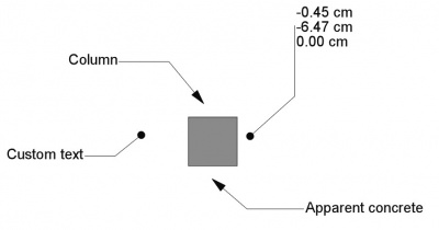
Various labels with different orientations, arrows and information
Usage
See also: Draft Tray, Draft Snap and Draft Constrain.
- Optionally select an object or a sub-element (vertex, edge or face) that you want to display attributes of.
- There are several ways to invoke the command:
- Press the
 Label button.
 - Select the Annotation → Label option from the menu.
- Use the keyboard shortcut: D then L.
- Press the
- The Label task panel opens. See Options for more information.
- If you have selected an element: select an option from the Label Type dropdown list. See Label types below.
- Pick the first point in the 3D View, or type coordinates and press the
 Enter Point button. This point indicates the target (arrow head). This can be anywhere, it does not have to be on an element.
 - Pick the second point in the 3D View, or type coordinates and press the Enter Point button. This point indicates the start of the horizontal or vertical segment of the leader.
- Pick the third point in the 3D View, or type coordinates and press the Enter Point button. This point indicates the base point of the text.
Options
The single character keyboard shortcuts available in the task panel can be changed. See Draft Preferences. The shortcuts mentioned here are the default shortcuts.
- To manually enter coordinates enter the X, Y and Z component, and press Enter after each. Or you can press the Enter Point button when you have the desired values. It is advisable to move the pointer out of the 3D View before entering coordinates.
- Press R or click the Relative checkbox to toggle relative mode. If relative mode is on, coordinates are relative to the last point, if available, else they are relative to the coordinate system origin.
- Press G or click the Global checkbox to toggle global mode. If global mode is on, coordinates are relative to the global coordinate system, else they are relative to the working plane coordinate system.
- Press S to switch Draft snapping on or off.
- Press Esc or the Close button to abort the command.
Label types
The following label types are available:
Custom: displays the contents of DataCustom Text.Name: displays the internal name of the target object. The internal name is assigned when an object is created and remains fixed throughout the existence of the object.Label: displays the label of the target object. The label of an object can be changed by the user.Position: displays the coordinates of the base point of the target object or of the target vertex.Length: displays the length of the target object or subelement.Area: displays the area of the target object or subelement.Volume: displays the volume of the target object.Tag: displays theTagattribute of the target object. Objects created with the BIM Workbench can have this attribute.Material: displays the label of the material of the target object.Label + PositionLabel + LengthLabel + AreaLabel + VolumeLabel + Material
Notes
- introduced in 1.1: A Draft Label can be edited with the Draft Edit command.
- The direction of the second segment of the leader determines the alignment of the text. If the segment is horizontal and pointing to the right the text is aligned to the left and vice versa. If the second segment goes vertically up, the text is aligned to the left. If it goes vertically down, the text is aligned to the right.
- Draft Labels created or saved with FreeCAD version 0.21 are not backward compatible.
Properties
See also: Property View.
A Draft Label object is derived from an App FeaturePython object and inherits all its properties. The following properties are additional unless otherwise stated:
Data
Label
- DataCustom Text (
StringList): specifies the contents of the text if DataLabel Type isCustom. Each item in the list represents a new text line. - DataLabel Type (
Enumeration): specifies the type of information displayed by the label. See Label types. - DataPlacement (
Placement): specifies the position of the text in the 3D View and, unless DataStraight Direction isCustom, also of the first leader segment, which is the segment where the text is attached. See Placement. - DataText (
StringList): (read-only) specifies the contents of the text that is actually displayed. Each item in the list represents a new text line.
Leader
- DataPoints (
VectorList): specifies the points of the leader. - DataStraight Direction (
Enumeration): specifies the direction of the first leader segment:Custom,HorizontalorVertical. - DataStraight Distance (
Distance): specifies the length of the first leader segment. Only used if DataStraight Direction isHorizontalorVertical. If the distance is positive, the leader starts from the right side of the text and the text aligns to the right. Otherwise the leader starts from the left side of the text and the text aligns to the left.
Target
- DataTarget (
LinkSub): specifies the object and optional subelement the label is linked to. - DataTarget Point (
Vector): specifies the position of the tip of the leader, which is where the arrow is attached.
View
Annotation
- ViewAnnotation Style (
Enumeration): specifies the annotation style applied to the label. See Draft AnnotationStyleEditor. - ViewScale Multiplier (
Float): specifies the general scaling factor applied to the label.
Display Options
- ViewDisplay Mode (
Enumeration): specifies how the text is displayed. If it isWorldthe text will be displayed on a plane defined by the DataPlacement of the label. If it isScreenthe text will always face the screen. This is an inherited property. The mentioned options are the renamed options (introduced in 0.21).
Graphics
- ViewArrow Size Start (
Length): specifies the size of the symbol displayed at the start of the leader. introduced in 1.1 - ViewArrow Type Start (
Enumeration): specifies the type of symbol displayed at the start of the leader, which can beDot,Circle,Arrow,Tick,Tick-2orNone. introduced in 1.1 - ViewFrame (
Enumeration): specifies what type of frame is drawn around the text. The current options areNoneorRectangle. - ViewLine (
Bool): specifies whether to display the leader line. If it isfalseonly the arrow and the text are displayed. - ViewLine Color (
Color): specifies the color of the leader and the arrow. This is also used for the frame. - ViewLine Width (
Float): specifies the width of the leader. This is also used for the frame.
Text
- ViewFont Name (
Font): specifies the font used to draw the text. It can be a font name, such asArial, a default style such assans,seriformono, a family such asArial,Helvetica,sans, or a name with a style such asArial:Bold. If the given font is not found on the system, a default font is used instead. introduced in 0.21 - ViewFont Size (
Length): specifies the size of the letters. The text can be invisible in the 3D View if this value is very small. introduced in 0.21 - ViewJustification (
Enumeration): specifies the horizontal alignment of the text:Left,CenterorRight. Only used if DataStraight Direction isCustom. Otherwise the horizontal alignment is based on the sign (positive or negative) of DataStraight Distance. - ViewLine Spacing (
Float): specifies the factor applied to the default line height of the text. - ViewMax Chars (
Integer): specifies the maximum number of characters on each line of the text. - ViewText Alignment (
Enumeration): specifies the vertical alignment of the text:Top,MiddleorBottom. - ViewText Color (
Color): specifies the color of the text.
Scripting
See also: Autogenerated API documentation and FreeCAD Scripting Basics.
To create a Draft Label use the make_label method (introduced in 0.19) of the Draft module. This method replaces the deprecated makeLabel method.
label = make_label(target_point=App.Vector(0, 0, 0),
                   placement=App.Vector(30, 30, 0),
                   target_object=None, subelements=None,
                   label_type="Custom", custom_text="Label",
                   direction="Horizontal", distance=-10,
                   points=None)
Example:
import FreeCAD as App
import Draft

doc = App.newDocument()

rectangle = Draft.make_rectangle(4000, 1000)
doc.recompute()

p1 = App.Vector(-200, 1000, 0)
place1 = App.Placement(App.Vector(-1000, 1300, 0), App.Rotation())

label1 = Draft.make_label(p1, place1, target_object=rectangle, distance=500, label_type="Label")
label1.ViewObject.FontSize= 200

p2 = App.Vector(-200, 0, 0)
place2 = App.Placement(App.Vector(-1000, -300, 0), App.Rotation())

label2 = Draft.make_label(p2, place2, target_object=rectangle, distance=500, label_type="Custom",
                          custom_text="Beware of the sharp edges")
label2.ViewObject.FontSize= 200

p3 = App.Vector(1000, 1200, 0)
place3 = App.Placement(App.Vector(2000, 1800, 0), App.Rotation())

label3 = Draft.make_label(p3, place3, target_object=rectangle, distance=-500, label_type="Area")
label3.ViewObject.FontSize= 200

doc.recompute()
This page is retrieved from https://wiki.freecad.org/Draft_Label