|
|
| Menu location |
|---|
| Utilities → Working Plane |
| Workbenches |
| Draft, BIM |
| Default shortcut |
| Draft: W P |
| Introduced in version |
| - |
| See also |
| Draft WorkingPlaneProxy |
Description
The ![]() Draft SelectPlane command defines the current Draft working plane. This is the plane in the 3D View where new Draft objects are created. A working plane can be based on one of several presets or on a selection. The selection can be created before (pre-selection) or after (post-selection) starting the command.
Draft SelectPlane command defines the current Draft working plane. This is the plane in the 3D View where new Draft objects are created. A working plane can be based on one of several presets or on a selection. The selection can be created before (pre-selection) or after (post-selection) starting the command.
introduced in 1.0: For each 3D View a separate working plane is stored.
The ![]() button in the Draft Tray changes depending on the current working plane. introduced in 1.0: If the working plane is not set to Auto an asterisk (*) is appended to the button label if the origin of the working plane does not match the global origin.
button in the Draft Tray changes depending on the current working plane. introduced in 1.0: If the working plane is not set to Auto an asterisk (*) is appended to the button label if the origin of the working plane does not match the global origin.
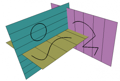
Shapes created on different working planes
Usage with pre-selection
- Do one of the following:
- Select a single object. The following objects are supported:
- Draft WorkingPlaneProxies: the ViewView Data (the camera position) and the ViewVisibility Map (the saved visibility of objects) of the working plane proxy are also restored.
- Arch Axes (introduced in 1.0)
- Arch AxisSystems (introduced in 1.0)
- Arch BuildingParts
- Arch SectionPlanes
- Std Parts: to avoid selecting subelements it is advisable to select these in the Tree View.
- Non-solid objects that consist of a single flat face or a single curved edge, or (introduced in 1.0) that have three or more vertices.
- Solid objects or objects without a shape that have a DataPlacement property. (introduced in 1.0)
- Select one or more subelements. You can select:
- A planar face.
- A curved edge.
- Three vertices.
- An edge and a vertex, or two edges. The combined vertices must define a plane. (introduced in 1.0)
- A planar face and an edge. (introduced in 1.1)
- A vertex. The working plane will move its origin to that vertex without changing its orientation (introduced in 1.2)
- Two vertices. The working plane will move the origin to the first selected vertex and align the X-axis from the first toward the second. (introduced in 1.2)
- Select a single object. The following objects are supported:
- There are several ways to invoke the command:
- Press the
 button in the Draft Tray.
 - Draft: Select the Utilities →
 Working Plane option from the menu, or from the Tree View or 3D View context menu.
 - Draft: Use the keyboard shortcut: W then P.
- Press the
- The working plane and the button in the Draft Tray are updated.
Usage with post-selection
- Invoke the command as explained above.
- The Working Plane Setup task panel opens. See Options for more information.
- Do one of the following:
- Select a single object. See the previous paragraph.
- Select one or more subelements. See the previous paragraph.
- Click anywhere in the 3D View to confirm the selection and finish the command.
- The working plane and the button in the Draft Tray are updated.
Usage with presets
- Invoke the command as explained above.
- The Working Plane Setup task panel opens. See Options for more information.
- Press any of the buttons to finish the command.
- The working plane and the button in the Draft Tray are updated.
Options
- Press the
 Top (XY) button to align the working plane with the XY-plane of the global coordinate system.
 - Press the
 Front (XZ) button to align the working plane with the XZ-plane of the global coordinate system.
 - Press the
 Side (YZ) button to align the working plane with the YZ-plane of the global coordinate system.
 - Press the
 Align to View button to align the working plane with the current 3D View. If the Center plane on view checkbox is not checked the working plane origin will match the origin of the global coordinate system, else it will match the center of the current 3D View.
 - Press the
 Automatic button to set the working plane to Auto. A working plane set to Auto will automatically align with the current 3D View whenever a Draft or BIM command requiring point input is started. This is equivalent to pressing the Align to View button before using the command. Additionally the working plane will align to planar faces that have been selected before starting the command, or when points on planar faces are picked during the command.
 - The Offset defines the perpendicular distance between the calculated plane and the actual working plane.
- Check the Center plane on view checkbox to put the origin of the working plane in the center of to the current 3D View. This option can be useful in combination with the Align to View button.
- Select a vertex in the 3D View and press the
 Move Working Plane button to move the working plane so that its origin matches the position of the selected vertex.
 - The Grid color button allows to quickly change the color of the grid. introduced in 1.0
- The Grid spacing defines the distance between grid lines.
- The Major lines every value determines where major grid lines are drawn. Major grid lines are slightly thicker than minor grid lines. For example if the grid spacing is
0.5 mand there is a main line every10 squares, such a line will occur every5 m. - The Grid size value determines the number of squares in the X and Y direction of the grid.
- The Snapping radius is the maximum distance at which Draft Snap Grid detects the intersections of grid lines.
- Press the
 Center View button to align the 3D View with the current working plane.
 - Press the
 Previous button to reset the working plane to its previous position.
 - Press the Next
 button to reset the working plane to its next position. introduced in 1.0
 - Press Esc or the Close button to abort the command.
Notes
- It can be useful to align the 3D View with the selected Draft working plane. For example after switching the working plane to Front you may want to switch to the Front view as well.
- The grid can be toggled with the Draft ToggleGrid command.
- By double-clicking Draft WorkingPlaneProxies in the Tree View you can quickly switch between working planes.
Preferences
See also: Preferences Editor and Draft Preferences.
- The grid settings in the task panel as well as several other grid settings are available as preferences: Edit → Preferences → Draft → Grid and Snapping.
- The Snapping radius can also be changed on-the-fly (see Draft Snap) or by changing: Tools → Edit Parameters → BaseApp → Preferences → Mod → Draft → snapRange.
Scripting
See also: Autogenerated API documentation and FreeCAD Scripting Basics.
The WorkingPlane module offers two classes to create working plane objects: the PlaneBase class and the PlaneGui class. The second class inherits from the first. Objects of the PlaneGui class interact with the GUI (the Draft Tray button), the 3D View and the grid. PlaneBase objects do not.
Use the get_working_plane() method of the WorkingPlane module to get an instance of the PlaneGui class linked to the current 3D View. The method either returns the existing working plane linked to the view or creates a new working plane if required.
import FreeCAD as App
import WorkingPlane

wp = WorkingPlane.get_working_plane()

origin = App.Vector(0, 0, 0)
normal = App.Vector(1, 1, 1).normalize()
offset = 17
wp.align_to_point_and_axis(origin, normal, offset)

point = App.Vector(10, 15, 2)
projection = wp.project_point(point)
print(projection)
The PlaneBase class can be used to create working planes independent of the GUI:
import WorkingPlane

wp = WorkingPlane.PlaneBase()
This page is retrieved from https://wiki.freecad.org/Draft_SelectPlane