Introduction
The Tree View appears in the upper section of the Model panel (if the Combo View is active) or as a stand-alone panel. It shows all user defined objects that are part of a FreeCAD document. The Tree View is a representation of the document's structure, and indicates what information is saved to disk.
These objects don't necessarily have to be geometrical shapes visible in the 3D View, but can also be supporting data objects created with any of the workbenches.
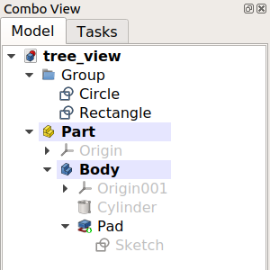
The Tree View showing various elements in the document.
Working with the Tree View
By default, whenever a new object is created, it is added to the end of the list in the Tree View. The Tree View allows managing the objects to keep them organized; it permits creating groups, moving objects inside groups, moving groups inside other groups, relabeling objects, copying objects, deleting objects, and using options from its context menu.
Many operations create objects that are dependent on a previously existing object. In this case, the Tree View shows this relationship by absorbing the older object inside the new object. Expanding and collapsing the objects in the Tree View shows the parametric history of that object. Objects that are deeper inside others are older, while objects that are outside are newer, and are derived from the older objects. By modifying the interior objects, the parametric operations propagate all the way to the top, generating a new result.
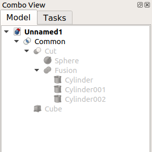
The topmost object is created by doing parametric operations on objects which themselves were created by previous operations.
Fully expanding the tree reveals the original elements that were used to create the partial solids.
Tree View columns
The Tree View always displays a column with the icons and labels of objects. Two additional columns can optionally be displayed as well. To enable these columns right-click the Tree View and in the context menu select Tree Settings and then Show Description (introduced in 0.21) and/or Show Internal Name (introduced in 1.0). Column headings are added if more than one column is displayed. Note that the internal names of objects cannot be changed.
Edit object label
Select an object in the first column and press F2 (on Windows and Linux), or Enter (on macOS), to edit its DataLabel property. This property can also be edited via the context menu option Rename or in the Property View.
Edit object description
An object can optionally have a description. This information is stored in its DataLabel2 property. If the description column is displayed you can edit this property by selecting an object in that column and pressing F2 (on Windows and Linux), or Enter (on macOS). The property can also be changed in the Property View.
The options in the context menu of the Tree View depend on the selected object(s) and the currently active workbench. To display this menu right-click the background of the list, right-click an object in the list, or select multiple objects in the list and then right-click one of them.
Keyboard modifiers
The usual keyboard modifiers can be used in the Tree View. The modifiers can be combined as well.
- Ctrl: hold down this key to select multiple objects.
- Shift: hold down this key to select all objects between a previously selected object and the next selected object.
Keyboard shortcuts
The following keyboard shortcuts are available when the focus is on the Tree View:
- Ctrl+F: opens a search box at the bottom of the tree, allowing to search and reach objects using their internal names or labels. To hide this search box, click inside it so that it has the focus and press Esc.
- Expand and collapse actions using Alt+Arrow combinations: introduced in 0.20
- Alt+Left: collapses selected item(s).
- Alt+Right: expands selected item(s).
- Alt+Up: expands selected item(s) with all their tier-1 children collapsed (deeper children remain unchanged).
- Alt+Down: expands selected item(s) with all their tier-1 children expanded as well (deeper children remain unchanged).
Overlay icons
One or more overlay icons can be displayed on top of an object's default icon in the Tree View. The available overlay icons and their meaning are listed below.
 White check mark on blue background
This indicates that the object has to be recomputed, due to changes made to the model or because the user marked the object in the Tree View context menu to be recomputed. In most cases recomputes are triggered automatically, but sometimes they are delayed for performance reasons.
 White exclamation mark on red background
This indicates that the object has an error that needs to be fixed. After recomputing the whole document a tooltip describing the error is shown when you hover the mouse over the object in the Tree View. Note: All other objects depending on an object in such an error state will not be properly recomputed, thus they may still show some old state.
 Purple chain link
This is shown for sketches, PartDesign primitives, such as box, cylinder, etc. and Datum geometry. It indicates that the object is not attached to anything. It has no Attachment Offset and gets its position and alignment solely from its Placement property. There is a Basic Attachment Tutorial explaining how to handle such objects.
This icon is also shown for Assembly joints that are not connected (via other joints) to a grounded object.
 Yellow X
This is only used for sketches and indicates that the sketch is not fully constrained. If the sketch is in edit mode the number of remaining degrees of freedom is shown in the solver messages.
 White arrow on green background
This indicates the so called Tip of a PartDesign Body. It is usually the last feature in a body and represents the whole body to the world outside of the body, e.g. when the body is exported or used in Part boolean operations. The tip can be changed by the user.
 Red backslash
This indicates a suppressed PartDesign feature.
 White upwards curved arrow
This indicates a linked object.
 Two white upwards curved arrows
This indicates a linked object loaded from an external document.
 Eye symbol
This indicates that the object will be hidden in the Tree View if the Show Items Hidden in Tree View context menu option of objects or the document is unchecked. Objects that have their ViewShow In Tree property set to false are affected. This property can be changed in the Property View or with the Toggle Visibility in Tree View context menu option of objects.
 Cyan ice crystal
This indicates a frozen object that is not recomputed when its parents change.
Preferences
See Combo View.
This page is retrieved from https://wiki.freecad.org/Tree_View