|
|
| Menu location |
|---|
| Part Design → New Body |
| Workbenches |
| PartDesign |
| Default shortcut |
| None |
| Introduced in version |
| 0.17 |
| See also |
| Std Part, Feature editing |
Description
A PartDesign Body is the base element to create solids shapes with the PartDesign Workbench. It can contain sketches, datum objects, and PartDesign Features that help in building a solid object. A Body is intended to hold a single contiguous solid, but in FreeCAD version 1.0 an experimental property (DataAllow Compound) has been introduced to allow non-contiguous Bodies.
The Body provides an Origin object which includes local X-, Y- and Z-axes, standard planes and an origin point. These elements can be used as references to attach sketches and primitive objects.
Do not confuse the ![]() PartDesign Body with the
PartDesign Body with the ![]() Std Part. The first one is a specific object used in the
Std Part. The first one is a specific object used in the ![]() PartDesign Workbench, intended to model a solid object by means of PartDesign Features. The Std Part is a grouping object intended to create assemblies; it is not used for modelling, just to arrange different objects in space. Multiple bodies, and other Std Parts, can be placed inside a single Std Part to create a complex assembly.
PartDesign Workbench, intended to model a solid object by means of PartDesign Features. The Std Part is a grouping object intended to create assemblies; it is not used for modelling, just to arrange different objects in space. Multiple bodies, and other Std Parts, can be placed inside a single Std Part to create a complex assembly.


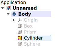
Left: the Tree View showing the features that sequentially produce the final shape of the object. Right: the final object visible in the 3D View.
Usage
If no previous solid is selected:
- There are several ways to invoke the tool:
- Press the
 New Body button.
 - Select the Part Design → New Body option from the menu.
- Press the
- An empty Body is created and automatically becomes active.
- Now you can press
 New Sketch to create a sketch in the Body that can be used with
  Pad.
Pad. - Alternatively, add a primitive PartDesign Feature, for example,
 Additive Box.
If a solid object is selected:
- There are several ways to invoke the tool:
- Press the New Body button.
- Select the Part Design → New Body option from the menu.
- Press the
- A new Body is created containing a single Base Feature. This Base Feature element is a simple reference to another object previously created or imported into the document. See Base Feature for more information. An existing Body or PartDesign Feature cannot be selected when pressing Body.
Properties
A PartDesign Body (PartDesign::Body class) is derived from a Part Feature (Part::Feature class), therefore it shares all the latter's properties.
In addition to the properties described in Part Feature, the PartDesign Body has the following properties in the Property View.
Data
Base
- DataTip (
Link): the PartDesign Feature defined as "Tip", which is usually the last feature created in the Body. The Tip indicates the final shape of the Body, which is shown in the 3D View when ViewDisplay Mode Body is set toTip. See Tip for more information. - DataBase Feature (
Link): an external shape used as the first PartDesign Feature in the Body. It is usually set when dragging a solid object into an empty Body. If no solid is imported in this way, this property will be empty. See Base Feature for more information. - Data (Hidden)Origin (
Link): the App Origin object that is the positional reference for all elements listed in DataGroup. - DataGroup (
LinkList): a list with the PartDesign Features in the Body. - Data (Hidden)_ Group Touched (
Bool): whether the group is touched or not.
Experimental
- DataAllow Compound (
Bool): allow multiple solids in the Body.
View
Base
- ViewDisplay Mode Body (
Enumeration): sets the display mode specifically for the Body with one of two types.Through(default) exposes all objects inside the Body, that is, sketches, PartDesign Features, datum objects, etc. This mode allows visualizing partial operations done inside the Body, and thus it is the recommended mode when adding and editing features. Select the specific feature, and the set ViewVisibility totrueor press the Space bar on the keyboard.Tipexposes only the final shape of the Body, which is defined by the DataTip property. Everything else, including sketches, partial features, datums, etc., is not displayed, even if they are visible in the Tree View. This mode is recommended when the Body does not need to be modified further, so a fixed shape is shown. This mode is also recommended when you wish to select the sub-elements (vertices, edges, and faces) of the final shape to use with other workbenches' tools.
Detailed explanation of the properties
Active status
An open document can contain multiple Bodies. To add a new feature to a specific Body, it needs to be made active. An active body will be displayed in the Tree View with the background color specified by the Active container value in the Preferences Editor. An active Body will also be shown in bold text.
To activate or de-activate a Body:
- Double click on it on the Tree View, or
- Open the context menu (right click) and select Active Body.
Activating a Body automatically switches to the PartDesign Workbench. Only a single Body can be active at a time.
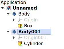
Document with two PartDesign Bodies, of which the second one is active.
Origin
The Origin consists of the three standard axes (X, Y, Z), three standard planes (XY, XZ and YZ) and an origin point. Sketches and other objects can be attached to these elements when creating them.
- Create the Body.
- If the Body is selected in the Tree View, press New Sketch; the task panel will open to allow selecting one of the planes.
- If the Body is not selected, select the Origin instead and make it visible in the 3D View by pressing the Space bar on the keyboard. Also expand the Origin object to see the axes and planes.
- Select one of the planes, either in the Tree View or in the 3D View, then press New Sketch. The sketch will be created on the chosen plane.
The same process can be used when creating datums.
Note 1: Each element of the Origin can be hidden and unhidden individually with the Space bar. This is useful to choose the correct reference when creating other objects.
Note 2: All elements inside the Body are referenced to the Body's Origin which means that the Body can be moved and rotated in reference to the global coordinate system without affecting the placement of the elements inside.
Base Feature
The Base Feature is the first PartDesign Feature in the Body when the Body is based on another solid shape. This solid can be created by any workbench, or imported from an external file, for example, a STEP file.
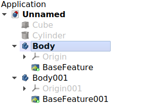
Two PartDesign Bodies, each with a single Base Feature taken from a previously created solid.
To create the Base Feature:
- select a solid shape external to any Body, and
- press New Body; this will create a new Body with a single Base Feature.
You can't select an existing Body, or any of its features, when pressing ![]() New Body. If you already have a Body, you can create the Base Feature in this way:
New Body. If you already have a Body, you can create the Base Feature in this way:
- in the Tree View, pick an object, and drag and drop it inside the Body, or
- in the Property View, edit the value of DataBase Feature by pressing the ellipsis …, and choosing an object from the list. In this case you can choose an existing Body to be the Base Feature.
The Base Feature is entirely optional; it is only present when including an object from outside the Body. If no external solid is included, you can still build your shape using sketches, pads, primitive objects, and other PartDesign Features. In this case the DataBase Feature property remains empty.
Note 1: dragging and dropping only works for Bodies which don't have a Base Feature already.
Note 2: if the Body already has several features, when you drag and drop the external solid, the Base Feature will be created at the beginning of the list of features, that is, it will be added to the beginning of the DataGroup property.
Note 3: If another PartDesign body is selected as a BaseFeature it must have a shape. If it is empty (no features, no BaseFeature, …) this will result in error.
Tip
The Tip is the PartDesign Feature that is exposed outside the Body; that is, if another tool from any workbench (for example, ![]() Part SimpleCopy or
Part SimpleCopy or ![]() Part Cut) needs to use the shape of the Body, it will use the shape of the Tip. Said in another way, the Tip is the final representation of the Body as if the parametric history didn't exist.
Part Cut) needs to use the shape of the Body, it will use the shape of the Tip. Said in another way, the Tip is the final representation of the Body as if the parametric history didn't exist.
The Tip is automatically set to the last feature created in the Body. Nevertheless, it can also be set to any of the intermediate features by opening the Tree View context menu (right-click) and choosing ![]() Set Tip, or by changing the Body's DataTip value in the Property View.
Set Tip, or by changing the Body's DataTip value in the Property View.
Changing the Tip in effect rolls back its history, making it possible to add features that should have been added earlier. It also exposes a different shape to external tools.
In the Tree View, the Tip of the Body is recognized by the PartDesign Feature that has an overlay icon consisting of a white arrow inside a green circle.
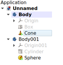
Two PartDesign Bodies, each of them with PartDesign Features. The Tip is the last feature in them, and is marked with an overlay symbol.
Interaction with other workbenches
By default, PartDesign Features inside a Body are selectable, as this is required to edit and add more features with the PartDesign Workbench tools. Nevertheless, selecting the individual features to use them with tools from other workbenches, like Part and Draft, is not advised, as the results may be unexpected; if this is done, in the Report View an error message may appear, Links go out of the allowed scope.
Therefore, for interactions with other workbenches, only the Body itself should be selected in the Tree View. In cases where it is necessary to select specific sub-elements of the Body (vertices, edges, and faces), the Body's ViewDisplay Mode Body property should be switched to Tip. When this mode is enabled, access to objects under the Body (features, datums, sketches) is disabled, and everything but the Body's Tip will be hidden in the 3D View.
Once the sub-elements have been used with other workbenches, ViewDisplay Mode Body can be set back to Through.

Left: when "Display Mode Body" is set to Through it is possible to select and perform operations with the individual PartDesign Features; in general, this is not recommended. Right: when "Display Mode Body" is set to Tip all selections and operations done on the Body will be done on the Tip, making sure only the final shape of the Body is exposed.
Visibility management
The Body's visibility supersedes the visibility of any object it contains. If the Body is hidden, the objects it contains will be hidden as well, even if their individual ViewVisibility property is set to true.
Multiple Sketches may be visible at one time, but only one PartDesign Feature (solid result) can be visible at a time. Selecting a hidden feature and pressing the Space bar in the keyboard will make it visible, and automatically hide the previously visible feature.
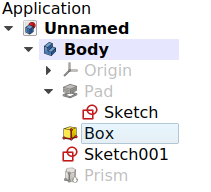
PartDesign Body: multiple Sketches may be visible simultaneously, but only one solid PartDesign Feature may be visible at one time, whether it is the Tip or not.
introduced in 1.2 If a Body is made visible while none of its features are visible, the current Tip is shown automatically so that the Body becomes visible in the 3D View.
Attachment
PartDesign Features, just like planar objects, can be attached to different planes, usually the standard planes defined by the Body's Origin, or to custom datums.
Sketches are normally attached to a plane when they are created. In a similar way, primitive features can also be attached. Attaching these objects to a plane allows them to be moved within the Body by changing their DataAttachment Offset property. For more information on the attachment modes see Part EditAttachment.
A PartDesign Feature that is not attached will be shown with a purple chainlink overlay icon in the Tree View.
PartDesign Body: PartDesign Features that are not attached to a plane or coordinate system will be shown with an overlay icon in the Tree View.
Inheritance
A PartDesign Body is formally an instance of the class PartDesign::Body, whose parent is Part Feature (Part::Feature class) through the intermediate Part::BodyBase class, and is augmented with an Origin extension.

Simplified diagram of the relationships between the core objects in the program. The PartDesign::Body object is intended to build parametric 3D solids, and thus is derived from the basic Part::Feature object, and has an Origin to control the placement of the features used inside of it.
Scripting
See also: FreeCAD Scripting Basics, and scripted objects.
See Part Feature for the general information on adding objects to the document
A PartDesign Body is created with the addObject() method of the document. Once a Body exists, PartDesign Features can be added to it with the addObject() or addObjects() methods of this Body.
import FreeCAD as App

doc = App.newDocument()
obj = App.ActiveDocument.addObject("PartDesign::Body", "Body")
obj.Label = "Custom label"

feat1 = App.ActiveDocument.addObject("PartDesign::AdditiveBox", "Box")
feat2 = App.ActiveDocument.addObject("PartDesign::AdditiveCylinder", "Cylinder")

obj.addObjects([feat1, feat2])
App.ActiveDocument.recompute()
In a document that has many Bodies, the active Body can be set using the setActiveObject method of the ActiveView. The first argument is the fixed string "pdbody", and the second argument is the Body object that should be made active.
import FreeCAD as App
import FreeCADGui as Gui

doc = App.newDocument()
obj1 = App.ActiveDocument.addObject("PartDesign::Body", "Body")
obj2 = App.ActiveDocument.addObject("PartDesign::Body", "Body")

Gui.ActiveDocument.ActiveView.setActiveObject("pdbody", obj1)
App.ActiveDocument.recompute()
This page is retrieved from https://wiki.freecad.org/PartDesign_Body