This documentation is not finished. Please help and contribute documentation.
GuiCommand model explains how commands should be documented. Browse Category:UnfinishedDocu to see more incomplete pages like this one. See Category:Command Reference for all commands.
See WikiPages to learn about editing the wiki pages, and go to Help FreeCAD to learn about other ways in which you can contribute.
|
|
| Menu location |
|---|
| Part Design → Additive Features → Pad |
| Workbenches |
| PartDesign |
| Default shortcut |
| None |
| Introduced in version |
| - |
| See also |
| PartDesign Pocket |
Description
The Pad tool extrudes a sketch or a face along a straight path.

Sketch (A) on the left; end result after pad operation (B) on the right
Usage
- Select a single sketch or one or more faces from the Body.
- There are several ways to invoke the tool:
- Press the
 Pad button.
 - Select the Part Design → Additive Features → Pad option from the menu.
- Press the
- Set the Pad parameters, see Options below.
- Press the OK button.
Options
When creating a pad, or after double-clicking an existing pad in the Tree View, the Pad parameters task panel is shown. It offers the following settings:
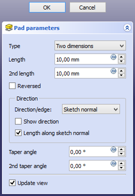
Type
Type offers five different ways of specifying the length of the pad:
Dimension
Enter a numeric value for the Length of the pad. With the option Symmetric to plane the pad will extend half the given length to either side of the sketch or face.
To last
The pad will extend up to the last face of the support it encounters in its direction. If there is no support, an error message will appear.
To first
The pad will extend up to the first face of the support it encounters in its direction. If there is no support, an error message will appear.
Up to face
The pad will extend up to a face. Press the Select face button and select a face or a datum plane from the Body.
Two dimensions
This allows to enter a second length in which the pad should extend in the opposite direction. The directions can be switched by checking the Reversed option.
Up to shape
introduced in 1.0: The pad will extend up to the selected shape. Optionally press the Select shape button and select a shape. Leave the Select all faces checkbox enabled or disable it, press the Select faces button and select the faces up to which the pad should be created.
Offset to face
Offset from face at which the pad will end. This option is only available if Type is To last, To first or Up to face.
Length
Defines the length of the pad. This option is only available if Type is Dimension or Two dimensions. The length is measured along the direction vector, or along the normal of the sketch or face. Negative values are not possible. Use the Reversed option instead.
2nd length
Defines the length of the pad in the opposite direction. This option is only available if Type is Two dimensions.
Symmetric to plane
Check this option to extrude half the given length to either side of the sketch or face. This option is only available if Type is Dimension.
Reversed
Reverses the direction of the pad.
Direction
Direction/edge
You can select the direction of the extrusion:
- Sketch normal or Face normal: The sketch or face is extruded in the direction of its normal. If you have selected several sketches or faces to be extruded, the normal of the first one will be used.
- Select reference…: The sketch or face is extruded in the direction of a straight edge or a datum line selected from the Body.
- Custom direction: The sketch or face is extruded in the direction of the specified vector.
Show direction
If checked, the pad direction will be shown. In case the pad uses a Custom direction, it can be changed.
Length along sketch normal
If checked, the pad length is measured along the sketch or face normal, otherwise along the custom direction.
Taper angle
Tapers the pad in the extrusion direction by the given angle. A positive angle means the outer pad border gets wider. Note that inner structures receive the opposite taper angle. This is done to facilitate the design of molds and molded parts. This option is only available if Type is Dimension or Two dimensions.
2nd taper angle
Tapers the pad in the opposite extrusion direction by the given angle. See Taper angle. This option is only available if Type is Two dimensions.
Properties
Data
Pad
- DataType (
Enumeration): Defines how the pad will be extruded, see Options. - DataLength (
Length): Defines the length of the pad, see Options. - DataLength2 (
Length): Second pad length in case the DataType is TwoLengths, see Options. - DataUse Custom Vector (
Bool): If checked, the pad direction will not be the normal vector of the sketch but the given vector, see Options. - DataDirection (
Vector): Vector of the pad direction if DataUse Custom Vector is used. - DataReference Axis (
LinkSub) - DataAlong Sketch Normal (
Bool): If true, the pad length is measured along the sketch normal. Otherwise and if DataUse Custom Vector is used, it is measured along the custom direction. - DataUp To Face (
LinkSub): A face the pad will extrude up to, see Options. - DataOffset (
Length): Offset from face in which the pad will end. This is only taken into account if the DataType option UpToLast, UpToFirst or UpToFace is used. - DataTaper Angle (
Angle) - DataTaper Angle2 (
Angle)
Part Design
- DataRefine (
Bool): True or false. Cleans up residual edges left after the operation. This property is initially set according to the user's settings (found in Preferences → Part Design → General → Model settings).
Sketch Based
- DataProfile (
LinkSub) - DataMidplane (
Bool) - DataReversed (
Bool) - DataAllow Multi Face (
Bool)
Limitations
- Like all Part Design features, Pad creates a solid, thus the sketch must include a closed profile or it will fail with a Wire is not closed error.
- Sketches containing B-Splines often cannot be tapered properly. This is a limitation of the OpenCASCADE kernel that FreeCAD uses.
- For larger angles tapering will fail if the end face would have fewer edges than the start face/sketch.
- The algorithm used for To First and To Last is:
- Create a line through the center of gravity of the sketch
- Find all faces of the support cut by this line
- Choose the face where the intersection point is nearest/furthest from the sketch
- This means that the face that is found might not always be what you expected. If you run into this problem, use the Up to face type instead, and pick the face you want.
- For the very special case of extrusion to a concave surface, where the sketch is larger than this surface, extrusion will fail. This is an unresolved bug.
This page is retrieved from https://wiki.freecad.org/PartDesign_Pad