|
|
| Menu location |
|---|
| 3D/BIM → Space |
| Workbenches |
| BIM |
| Default shortcut |
| S P |
| Introduced in version |
| 0.14 |
| See also |
| None |
Description
The Arch Space tool allows you to define an empty volume, either by basing it on a solid shape, or by defining its boundaries, or a mix of both. If it is based solely on boundaries, the volume is calculated by starting from the bounding box of all the given boundaries, and subtracting the spaces behind each boundary. The Space object always defines a solid volume. The floor area of a space object, calculated by intersecting a horizontal plane at the center of mass of the space volume, can also be displayed.
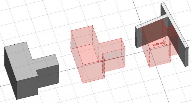
Space object created from an existing solid object, then two wall faces are added as boundaries.
Usage
- Select an existing solid object, or faces on boundary objects.
- Invoke the command using several methods:
- Pressing the
 Space button in the toolbar.
 - Using the S then P keyboard keys
- Using the 3D/BIM → Space entry from the top menu
- Pressing the
Once a space has been created, you can also add or remove boundaries to/from it using the ![]() Add Component or
Add Component or ![]() Remove Component buttons in the toolbar. Alternatively, you can also do this in the Tasks panel or in the Property View.
Remove Component buttons in the toolbar. Alternatively, you can also do this in the Tasks panel or in the Property View.
As an example, to add a boundary, given a space that intersects a wall:
- Select the wall face that intersects the space. That will be the new boundary.
- Keeping the Ctrl key pressed, select the space.
- Press the
 Add Component button in the toolbar.
 - The wall face now defines a new boundary, and the space will only extend up to the wall face in the direction facing it.
The same example: add a boundary, given a space that intersects a wall. This time we're using the Tasks panel:
- Double-click the space object in the Tree View. This will activate its Tasks panel.
- Select the wall face that intersects the space. That will be the new boundary.
- Press the Add Component button in the Tasks panel. The name of the wall face will be displayed in the "Space boundaries" section there.
- Press the OK button in the Tasks panel.
- The wall face now defines a new boundary, and the space will only extend up to the wall face in the direction facing it.
Yet another alternative: add a boundary, given a space that intersects a wall. This time we're using the Property View:
- Navigate to the Property View and locate the DataBoundaries property under the "Space" group.
- On the right hand side of the DataBoundaries property, click on the ellipsis button.
- Select the wall face that intersects the space. That will be the new boundary. The "Link" dialog will reflect your selection.
- Press the OK button in the "Link" dialog.
- The wall face now defines a new boundary, and the space will only extend up to the wall face in the direction facing it.
Limitations
- Non-convex footprints are not supported (issue #6091)
- Volume subtractions are not supported (issue #24579 and workaround).
- The boundaries properties is currently not editable via GUI.
- See the forum announcement.
Properties
An Arch Space object shares the common properties and behaviors of all Arch Components.
Data
Space
- DataArea (
Area): The computed floor area of this space (read-only). Identical to the underlying Arch Component's DataHorizontal Area property. - DataArea Calculation Type (
Enumeration): Defines the calculation type for the horizontal area and its perimeter length:XY-plane projection: Area is calculated from the space's footprint, that is, its projection on the XY-plane. Suitable for spaces with variable heights (e.g. directly under a roof at an angle, with domes, arches, etc).At Center of Mass: Area is calculated from the space's center of mass. Suitable for a space that has level changes, or a footprint that is based on multiple faces and yet the main area is above the ground (e.g. a table-like space).
- DataAuto Power (
Bool): If True, Equipment Power will be automatically filled by the equipment included in this space. - DataBoundaries (
LinkSubList): The objects that make the boundaries of this space object. - DataConditioning (
Enumeration): The type of air conditioning of this space. - DataEquipment Power (
Float): The electric power needed by the equipment of this space in Watts. - DataFinish Ceiling (
String): The finishing of the ceiling of this space. - DataFinish Floor (
String): The finishing of the floor of this space. - DataFinish Walls (
String): The finishing of the walls of this space. - DataFloor Thickness (
Length): The thickness of the floor finish. - DataGroup (
LinkList): Objects that are included inside this space, such as furniture - DataInternal (
Bool): Specifies if this space is internal or external. - DataLighting Power (
Float): The electric power needed to light this space in Watts. - DataNumber Of People (
Integer): The number of people who typically occupy this space. - DataSpace Type (
Enumeration): The type of this space.
View
Space
- ViewDecimals (
Integer): The number of decimals to use for calculated texts. - ViewFirst Line (
Length): The size of the first line of text (multiplies the font size. 1 = same size, 2 = double size, etc..). - ViewFont Name (
Font): The name of the font. - ViewFont Size (
Length): The size of the text. - ViewLine Spacing (
Float): The space between the lines of text. - ViewShow Unit (
Bool): Show the unit suffix or not. - ViewText (
StringList): The text to show. Use $area, $label, $longname, $description or any other propery name preceded with $ (case insensitive), or $floor, $walls, $ceiling for finishes, to insert the respective data. - ViewText Align (
Enumeration): The justification of the text. - ViewText Color (
Color): The color of the text. - ViewText Position (
VectorDistance): The position of the text. Leave (0,0,0) for automatic position.
Options
- To create zones that group several spaces, use an Arch Floor and optionally set its IFC type to "Spatial Zone". The area of the floor will be calculated as the sum of all children spaces. Note that for this to work, the spaces need to be direct children (e.g. they cannot be in a group beneath the floor)
- The Space object has the same display modes as other Arch and Part objects, with one more, called Footprint, that displays only the bottom face of the space.
Scripting
See also: Arch API and FreeCAD Scripting Basics.
The Space tool can be used in macros and from the Python console by using the following function:
Space = makeSpace(objects=None, baseobj=None, name="Space")
- Creates a
Spaceobject from the givenobjectsorbaseobj, which can be- one document object, in which case it becomes the base shape of the Space object, or
- a list of selection objects as returned by
FreeCADGui.Selection.getSelectionEx(), or - a list of tuples
(object, subobjectname)
Example:
import FreeCAD, Arch

Box = FreeCAD.ActiveDocument.addObject("Part::Box", "Box")
Box.Length = 1000
Box.Width = 1000
Box.Height = 1000

Space = Arch.makeSpace(Box)
Space.ViewObject.LineWidth = 2
FreeCAD.ActiveDocument.recompute()
After a space object is created, selected faces can be added to it with the following code:
import FreeCAD, FreeCADGui, Draft, Arch

points = [FreeCAD.Vector(-500, 0, 0), FreeCAD.Vector(1000, 1000, 0)]
Line = Draft.makeWire(points)
Wall = Arch.makeWall(Line, width=150, height=2000)
FreeCAD.ActiveDocument.recompute()

# Select a face of the wall
selection = FreeCADGui.Selection.getSelectionEx()
Arch.addSpaceBoundaries(Space, selection)
Boundaries can also be removed, again by selecting the indicated faces:
selection = FreeCADGui.Selection.getSelectionEx()
Arch.removeSpaceBoundaries(Space, selection)
This page is retrieved from https://wiki.freecad.org/Arch_Space