| Tema |
|---|
| Sketcher |
| Nivel |
| Beginner |
| Tiempo para completar |
| 15 minutes |
| Autores |
| Drei |
| Versión de FreeCAD |
| 0.16 or above |
| Archivos de ejemplos |
| Ver también |
| None |
Introduction
This tutorial is meant to introduce the reader to the basic workflow of the PartDesign Workbench. The reader will see how to create 3D objects based on Sketches, perform subtraction operations and how to replicate specific features in a pattern.
Requirements
- FreeCAD version 0.17 or above
- The reader has finished the Basic Sketcher Tutorial
Procedure
Creating 3D geometry
The purpose of the PartDesign Workbench is to allow the user to create geometry in 3D space. As such, it is equipped with tools to make use of sketches and convert them to 3D objects.
To achieve this, two tools are exist: ![]() Pad and
Pad and ![]() Revolution. Alongside their subtractive counterparts (
Revolution. Alongside their subtractive counterparts (![]() Pocket and
Pocket and ![]() Groove) they make up most of the common actions used by this workbench.
Groove) they make up most of the common actions used by this workbench.
- Switch to the PartDesign Workbench
- With the sketch selected in the Tree View, press
 PartDesign Body, choose the default XY-plane, and press OK. The sketch should appear now inside the Body.
 - Select
 Pad
Pad - Set the distance to 5 mm
- Select Ok
Another way to create 3D geometry is with the ![]() Revolution tool.
Revolution tool.
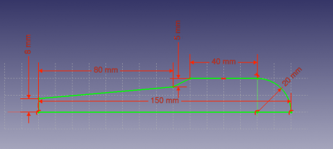
- Create a new body PartDesign Body, and then a sketch based on the image above.
- The sketch can be on any plane, but should be co-incident with the horizontal axis.
- Select
 Revolution
 - Set the "Axis" to the "Horizontal Sketch Axis"
- Set the angle to 360°
Subtracting Features
We'll begin by creating a sketch with the shape we want to subtract.
- Select the top flat face of the "Revolution"
- Select
 New Sketch
 - Select
 External Geometry
 - Approach the edge of the pad. An arc should be highlighted
- Select the arc. An arc of a different color should appear in the sketch
- Create a hexagon centered on the same point as the arc and set the radius of the reference circle to 5 mm
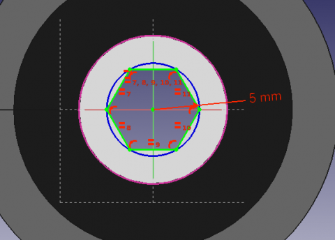
Afterwards, we'll proceed to apply a Pocket feature.
- Select the sketch
- Select
 Pocket
 - Set the distance to Through all
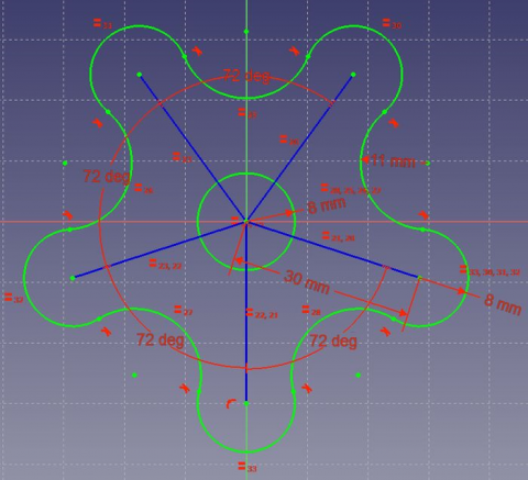
Pattern Features
Recall the extruded profile that was created at the start of the tutorial.
- Select the top face of the object
- Create a new Sketch
- Create reference geometry linked to the top arm of the figure
- Create a circle constrained to the center of the reference arc
- Set its radius to 3 mm
- Pocket the sketch through all the workpiece
Instead of creating a circle for each hole in the sketch, we will introduce the concept of Pattern Features. These tools operate by replicating a feature in the workpiece that has already been created and that we wish to reproduce in a linear or circular arrangement. We will use a combination of Linear and Polar pattern features simulatneously to obtain the final workpiece.
- Select the Pocket feature that we just created in the Tree View
- Select
 MultiTransform
In the Combo View we are now asked to introduce the Transformations that we desire. Notice that in the MultiTransform parameters menu we see that FreeCAD has identified the Pocket as the Original feature and a second box requests us to Right click it to introduce the pattern features.
- Right click the box
- Select Add Linear Pattern
- Set the Direction to Vertical Sketch Axis
- Set length to 10 mm
- Leave occurrences at 2
- Click OK
- Right click the box again to add a Polar Pattern. Notice that the 3D View has now added the linear pattern.
- Set occurrences to 5
- Click OK twice
After completing this task you should have the following result.
![]()
If not, re-edit the MultiTransform operation by double clicking on it in the Tree View. Check both pattern features to detect necessary modifications, such as the Axis and if the Direction needs to be reversed.
We are now finished with the basic workflow for the PartDesign Workbench.
Esta página ha sido recuperada de https://wiki.freecad.org/PartDesign_tutorial