This documentation is not finished. Please help and contribute documentation.
GuiCommand model explains how commands should be documented. Browse Category:UnfinishedDocu to see more incomplete pages like this one. See Category:Command Reference for all commands.
See WikiPages to learn about editing the wiki pages, and go to Help FreeCAD to learn about other ways in which you can contribute.
|
|
| Menu location |
|---|
| SheetMetal → Make Hem |
| Workbenches |
| SheetMetal |
| Default shortcut |
| Z |
| Introduced in version |
| - |
| See also |
| None |
Description
The ![]() SheetMetal AddHem command creates hems on selected edges. By changing the Dataangle property a flange it can be turned into a hem.
SheetMetal AddHem command creates hems on selected edges. By changing the Dataangle property a flange it can be turned into a hem.
A hem usually consists of a cylindrical bend of roughly 180° and a planar strip (wall).
![]()
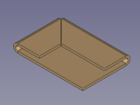
Two selected edges → two mitered hems
Usage
- Select one or more edges of a solid shape.
- There are several ways to invoke the command:
- A Hem object is created that consists of one new hem at each selected edge, and the Hem properties Task Panel opens:
- With the General tab selected:
- Optionally press the Select button to add more edges.
- Optionally press the Clear selection button to clear the list of selected edges.
- Press the Preview button to finish the selection and display the changes.
- Optionally adjust the bend parameters in this tab. See the General section of the Task Panel description below
- Optionally press the Select button to add more edges.
- Optionally switch to another tab to adjust more parameters. See Offsets, or Miter, section of the Task Panel description below.
- With the General tab selected:
- Press the OK button to finish the command and close the Task Panel.
- Optionally adjust the parameters in the Property View.
Task Panel
Double-click an existing Hem object in the Tree View to re-open the Task Panel and edit the parameters.
General

- Select: Changes the amount of edges in the base Object property.
- Type: Sets the HemType property.
 Flat activates these sub-options:
- Width: Sets the width property.
 Reverse the wall: Toggles the invert property.
- Width includes bend: Toggles the Include Bend property.
 Open: activates these sub-options:
- Width: Sets the width property.
- Reverse the wall: Toggles the invert property.
- Width includes bend: Toggles the Include Bend property.
- Opening: Sets the opening property.
 Tear Drop: activates these sub-options:
- Width: Sets the width property.
- Reverse the wall: Toggles the invert property.
- Width includes bend: Toggles the Include Bend property.
- Bend radius: Sets the radius property.
- Open: Toggles the opened property.
- Opening: Sets the opening property.
 Rolled: activates these sub-options:
- Bend radius: Sets the radius property.
- Open: Toggles the opened property.
- Roll angle: Sets the Roll Angle property.
- Position: Sets the Bend Type property.
- Unfold: Toggles the unfold property.
Offsets

- Gap A: Sets the gap1 property.
- Gap B: Sets the gap2 property.
- Rectangle and Round radio buttons: Toggle the relief Type property.
- Width: Sets the reliefw property.
- Depth: Sets the reliefd property.
Miter
(Not available for rolled hems)

- Auto Miter: Toggles the Auto Miter property.
- If checked:
- Minimum Gap: Sets the minGap property.
- Max Extend Distance: Sets the max Extend Dist property.
- If unchecked:
- Angle 1: sets the miterangle1 property.
- Angle 2: sets the miterangle2 property.
Notes
- See Create a sheet metal object for a basic workflow.
Properties
See also: Property View.
A SheetMetal Hem object is derived from a Part Feature object or, if it is inside a PartDesign Body, from a PartDesign Feature object, and inherits all its properties. It also has the following additional properties:
Data
Parameters
- DataBend Type (
Enumeration): "Bend Type".Material Outside(default),Material Inside,Thickness Outside. - DataHem Type (
Enumeration): "Type of Hem".Flat(default),Open,Teardrop,Rolled. - DataInclude Bend (
Bool): "Width includes bend geometry". Default:false. - DataRoll Angle (
Angle): "Roll Angle". Default angle:90,00°. - Database Object (
LinkSub): "Base Object". Link to the planar face to receive a hem. - Datagap1 (
Distance): "Gap from Left side". Default:0,00 mm. - Datagap2 (
Distance): "Gap from Right side". Default:0,00 mm. - Datainvert (
Bool): "Invert Bend Direction". Default:false. - Dataopened (
Bool): "Opened Hem". Default:false. - Dataopening (
Length): "Openening. of Hem". Default:1,00 mm - Dataradius (
Length): "Bend Radius", the default value depends on the radius property of the parent feature: - Datawidth (
Length): "Width of Wall". Default:10,00 mm.
Parameters Ex
- DataAuto Miter (
Bool): "Enable Auto Miter". Default:true. - Datakfactor (
FloatConstraint): "Location of Neutral Line. Caution: Using ANSI standards, not DIN.".
Default:0,50. K factor (also known as neutral factor) for the bend. Used to calculate bend allowance when unfolding. - Datamax Extend Dist (
Length): "Auto Miter maximum Extend Distance". Default:5,00 mm. - Datamin Gap (
Length): "Auto Miter Minimum Gap". Default:0,20 mm. - Datamin Relief Gap (
Length): "Minimum Gap to Relief Cut". Default:1,00 mm. - Dataunfold (
Bool): "Shows Unfold View of Current Bend". Default:false
trueunfolds the bend.
Parameters Miterangle
- Datamiterangle1 (
Angle): "Bend Miter Angle from Left Side". Default angle:0,00°. - Datamiterangle2 (
Angle): "Bend Miter Angle from Right Side". Default angle:0,00°.
Parameters Relief
- DataRelief Factor (
Float): "Relief Factor". Default:0,70. - DataUse Relief Factor (
Bool): "Use Relief Factor". Default:false. - Datarelief Type (
Enumeration): "Relief Type".Rectangle(default),Round. Enabled only when a gap value is set. - Datareliefd (
Length): "Relief Depth". Default:1,00 mm. Enabled only when a gap value is set. - Datareliefw (
Length): "Relief Width". Default:0,80 mm. Enabled only when a gap value is set.
This page is retrieved from https://wiki.freecad.org/SheetMetal_AddHem