|
|
| poziția meniului |
|---|
| Arch → Section Plane |
| Ateliere |
| Arch |
| scurtătură |
| S P |
| Prezentat în versiune |
| - |
| A se vedea, de asemenea, |
| Draft Shape2DView, TechDraw NewArch |
Descriere
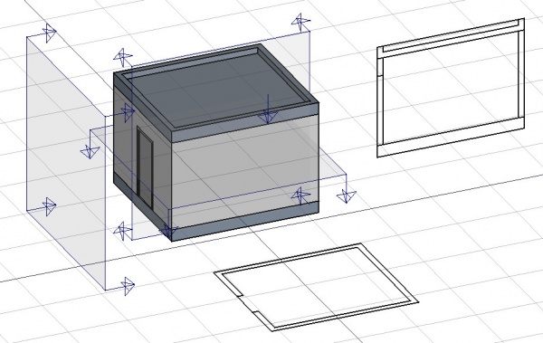
Acest instrumetn plasează în documentul curent un plan de secțiune gizmo, care definește secțiunea sau planul de vizualizare. Gizmo își ia locul în conformitate cu planul de lucru Draft Work Plan și poate fi mutat și reorientat prin mutarea și rotirea acestuia, până când descrie vizualizarea 2D pe care doriți să o obțineți. Obiectul plan de secțiune va lua în considerare numai un anumit set de obiecte. Obiectele selectate la crearea unei planuri de secțiune vor fi adăugate la setarea automată. Alte obiecte pot fi adăugate sau eliminate mai târziu dintr-un obiect SectionPlane cu ajutorul instrumentelor Arch Add și Remove Arch sau prin dublu clic pe planul de secțiuni din vizualizarea arborescentă.
The Section Plane object will only consider a certain set of objects. Objects that are selected when you create a Section Plane will be added to that set automatically. Other objects can later be added or removed from a SectionPlane object with the Arch Add and Arch Remove tools, or by double-clicking the Section Plane in the Tree View.
The Section Plane alone won't create any view of its objects set. For that, you must create a TechDraw ArchView to create a view in a TechDraw page.
Cum se folosește
- Optional, definiți Draft Working Plane pentru a reflecta planul unde dirți să plasați Section Plane
- Selectați obiecte pe care doriți să le includeți în vizualizarea secțiunii dvs
- Apăsați butonul
 SectionPlane sau apăsați tastele S apoi P
 - Move/rotate the Section Plane into correct position if needed
- Selectați Section Plane dacă nu este deja selectați
- Folosiți sau Drawing DraftView, Draft Shape2DView sau TechDraw ArchView pentru a crea o vizualizare
Typical drawing workflow

The typical workflow to create a 2D drawing involves the following steps, also reflected in the buttons' order in the toolbar:
- Create a
 Section Plane, and place it correctly in the model. As described before.
 - Create a drawing view with the
 2D Drawing tool. A drawing view is simply a BuildingPart that has been modified to be recognized as a 2D drawing (and stripped of some attributes like level, height, etc). Using a BuildingPart has a few advantages: It defines a working plane, you can move it and it will also move its contents, and it has a "title" that shows in the viewport. But fundamentally, the drawing view is just a container for the components of your 2D drawing. If the Section Plane is selected before initiating the 2D Drawing command, both the Section View and Section Cut objects mentioned in the next step are created automatically.
 - Create a
 Section View and if needed, a
  Section Cut from your Section Plane. Both tools produce a Shape2DView, but the first one in "solid" mode, which shows projected lines from what is viewed by the Section Plane, and the second one in "cut lines" mode, so it shows only the cut lines (the intersection between the Section Plane and the model). In plans and sections, you will want both, and give the section Cut a bit thicker line width, in elevations you will typically only need the section View, as there is nothing to cut. Then, of course, you place both these objects, in the drawing view.
 - Create all needed annotations like dimensions, texts, 2D linework, etc… and add them to the drawing view.
- Create a TechDraw page using the
 Page tool of the BIM Workbench. It will pop up a dialog to let you select an SVG file to use as a template (and remembers the last used template).
 - Once you have your drawing view and your page, select both and press the
 View button. This will create a TechDraw view on the page, showing the contents of your drawing view.
Opţiuni
- Planul de secțiune va considera doar un set de obiece , nu toate obiectele din document. Obiectele pot fi adăugate sau eliminate dintr-un obiect SectionPlane utilizând instrumentele Arch Add și Arch Remove sau făcând dublu clic pe planul de secțiuni din vizualizarea arborescentă, selectând obiecte fie în lista din Scena 3D și apăsarea butonului adăuga sau ștergeți.
- Cu un plan de secțiune obiect selectat, utilizați instrumentul Draft Shape2DView pentru a crea un obiect tip formă reprezentând vizualizarea secțiunii în document
- Create Drawing DraftViews if you are working with the Drawing Workbench, or TechDraw ArchView if you are using the TechDraw Workbench.
- Planul secțiunii poate fi, de asemenea, utilizat pentru a arăta întreaga vedere 3D tăiată printr-un plan infinit. Aceasta este doar vizuală și nu va afecta geometria obiectelor tăiate.

Proprietăți
Data
SectionPlane
- DateOnly Solids: If this is True, non-solid objects in the set will be disregarded
- VizualizareDisplay Length: The length of the section plane gizmo in the 3D view. Doesn't affect the resulting view
- VizualizareDisplay Height: The height of the section plane gizmo in the 3D view. Doesn't affect the resulting view
- VizualizareArrow Size: The size of the arrows of the section plane gizmo in the 3D view. Doesn't affect the resulting view
- VizualizareCut View: If this is true, the whole 3D view will be cut at the location of this section plane (experimental).

The Arch SectionPlane with the DateClip property set to true will behave like a camera, limiting the field of view.
View
SectionPlane
- VizualizareArrowSize: The size of the arrow symbol at the corners of the Section Plane in the 3D View. This value also controls the length of the lines indicating the view direction. Doesn't affect the resulting view.
- VizualizareCutDistance: This property is deprecated and has no effect. It was originally intended to create a thick visual slice in the 3D View.
- VizualizareCutMargin: A small offset distance to apply between the Section Plane and the actual real-time cut plane when VizualizareCutView is active. This helps prevent graphical artifacts (Z-fighting) on co-planar faces.
- VizualizareCutView: If
true, enables a real-time clipping effect in the 3D View, visually cutting through the model at the plane's location. - VizualizareDisplayHeight: The height of the Section Plane's visual representation in the 3D View. This dimension is also used to define the boundary of the 2D view when the DateClip data property is set to
true. - VizualizareDisplayLength: The width of the Section Plane's visual representation in the 3D View. This dimension is also used to define the boundary of the 2D view when the DateClip data property is set to
true. - VizualizareFontSize: The size of the label text that is displayed in the 3D View.
- VizualizareFontName: The font used for the label text.
- VizualizareShowLabel: If
true, the object's DateLabel will be displayed next to the Section Plane in the 3D View. - VizualizareTransparency: Controls the transparency of the Section Plane's face in the 3D View, from 0 (fully opaque) to 100 (fully invisible).
Tweaks
- Manually adding a property named RotateSolidRender of type App::PropertyAngle to the Section Plane's View properties (right-click the properties view, select Show hidden from the context menu, right-click again and select Add property) allows to rotate the render when using Solid mode. This is useful when a rendered view has for example both Arch and Draft elements, and the rendering of the Arch elements is rotated in relation to the Draft elements.
Alternative workflows
- The commands Draft Shape2DView and/or TechDraw ArchView can also be used to create a view from a Section Plane. However, it is recommended to use the dedicated BIM workbench tools described here instead.
Scripting
Scrip-Programare
Instrumentul Section Plane poate fi utilizat în macros și de la consola Python utilizând următoarele funcții:
Section = makeSectionPlane(objectslist=None, name="Section")
- Creates a Section plane objects including the given objects.
Exempluː
import FreeCAD, Draft, Arch

p1 = FreeCAD.Vector(0, 0, 0)
p2 = FreeCAD.Vector(2000, 0, 0)
baseline = Draft.makeLine(p1, p2)
baseline2 = Draft.makeLine(p1, -1*p2)

Wall1 = Arch.makeWall(baseline, length=None, width=150, height=2000)
Wall2 = Arch.makeWall(baseline2, length=None, width=150, height=1800)
Structure = Arch.makeStructure(length=1000, width=1000, height=200)
FreeCAD.ActiveDocument.recompute()

BuildingPart = Arch.makeBuildingPart([Wall1, Wall2])

Floor = Arch.makeFloor([BuildingPart])
Building = Arch.makeBuilding([Floor, Structure])
Site = Arch.makeSite(Building)
FreeCAD.ActiveDocument.recompute()

Section1 = Arch.makeSectionPlane([Wall1, Wall2])
Section2 = Arch.makeSectionPlane([Structure])
Section3 = Arch.makeSectionPlane([Site])
FreeCAD.ActiveDocument.recompute()
Această pagină este preluată de la https://wiki.freecad.org/Arch_SectionPlane