|
|
| Umístění Menu |
|---|
| Arch → Section Plane |
| Pracovní stoly |
| Arch |
| Výchozí zástupce |
| S P |
| Představen ve verzi |
| - |
| Viz také |
| Nikdo |
Popis
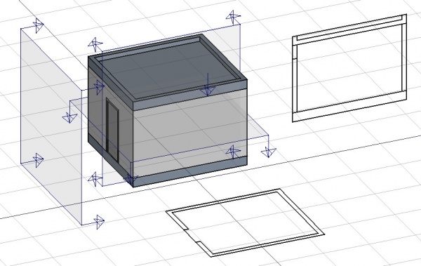
Tento nástroj umístí do aktuálního dokumentu pomůcku Rovina řezu, která definuje rovinu řezu nebo pohledu. Tato pomůcka může být přemístěna a přeorientována pomocí posunování a otáčení tak, abyste získali 2D pohled, který chcete získat. Objekt Rovina řezu bere ohled pouze na objekty, které byly vybrány v době jeho vytvoření. Objekty mohou být později přidávány do nebo odebírány z objektu Rovina řezu pomocí nástrojů Přidat a Odebrat.
The Section Plane object will only consider a certain set of objects. Objects that are selected when you create a Section Plane will be added to that set automatically. Other objects can later be added or removed from a SectionPlane object with the Arch Add and Arch Remove tools, or by double-clicking the Section Plane in the Tree View.
Po vytvoření objekt Rovina řezu také vkládá pohled sama sebe do aktivní Vykreslovací stránky nebo vytváří novou stránku, pokud žádná neexistuje. Můžete také přidat pohled Roviny řezu přímo do dokumentu použitím nástroje 2D kreslení s vybranou rovinou řezu.
Použití
Typical drawing workflow

The typical workflow to create a 2D drawing involves the following steps, also reflected in the buttons' order in the toolbar:
- Create a
 Section Plane, and place it correctly in the model. As described before.
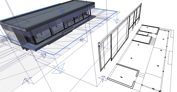
 - Create a drawing view with the
 2D Drawing tool. A drawing view is simply a BuildingPart that has been modified to be recognized as a 2D drawing (and stripped of some attributes like level, height, etc). Using a BuildingPart has a few advantages: It defines a working plane, you can move it and it will also move its contents, and it has a "title" that shows in the viewport. But fundamentally, the drawing view is just a container for the components of your 2D drawing. If the Section Plane is selected before initiating the 2D Drawing command, both the Section View and Section Cut objects mentioned in the next step are created automatically.
 - Create a
 Section View and if needed, a
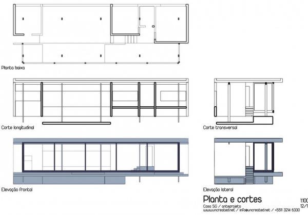
  Section Cut from your Section Plane. Both tools produce a Shape2DView, but the first one in "solid" mode, which shows projected lines from what is viewed by the Section Plane, and the second one in "cut lines" mode, so it shows only the cut lines (the intersection between the Section Plane and the model). In plans and sections, you will want both, and give the section Cut a bit thicker line width, in elevations you will typically only need the section View, as there is nothing to cut. Then, of course, you place both these objects, in the drawing view.
 - Create all needed annotations like dimensions, texts, 2D linework, etc… and add them to the drawing view.
- Create a TechDraw page using the
 Page tool of the BIM Workbench. It will pop up a dialog to let you select an SVG file to use as a template (and remembers the last used template).
 - Once you have your drawing view and your page, select both and press the
 View button. This will create a TechDraw view on the page, showing the contents of your drawing view.
Volby
- The Section Plane object will only consider a certain set of objects, not all the objects of the document. Objects can be added or removed from a SectionPlane object by using the Arch Add and Arch Remove tools, or by double-clicking the Section Plane in the Tree View, selecting objects either in the list of in the 3D View, and pressing the
 Add Selected or
  Remove buttons.
- S vybraným objektem Rovina řezu použijte nástroj 2D kreslení k vytvoření tvaru reprezentujícího pohled řezu v dokumentu
- The Section Plane can also be used to show the entire 3D View cut by an infinite plane when the PohledCutView property is set to
true. This is only visual, and won't affect the geometry of the objects being cut.

Vlastnosti
Data
SectionPlane
- PohledRozměr zobrazení: Velikost pomůcky Rovina řezu ve 3D pohledu

The Arch SectionPlane with the ÚdajeClip property set to true will behave like a camera, limiting the field of view.
View
SectionPlane
- PohledArrowSize: The size of the arrow symbol at the corners of the Section Plane in the 3D View. This value also controls the length of the lines indicating the view direction. Doesn't affect the resulting view.
- PohledCutDistance: This property is deprecated and has no effect. It was originally intended to create a thick visual slice in the 3D View.
- PohledCutMargin: A small offset distance to apply between the Section Plane and the actual real-time cut plane when PohledCutView is active. This helps prevent graphical artifacts (Z-fighting) on co-planar faces.
- PohledCutView: If
true, enables a real-time clipping effect in the 3D View, visually cutting through the model at the plane's location. - PohledDisplayHeight: The height of the Section Plane's visual representation in the 3D View. This dimension is also used to define the boundary of the 2D view when the ÚdajeClip data property is set to
true. - PohledDisplayLength: The width of the Section Plane's visual representation in the 3D View. This dimension is also used to define the boundary of the 2D view when the ÚdajeClip data property is set to
true. - PohledFontSize: The size of the label text that is displayed in the 3D View.
- PohledFontName: The font used for the label text.
- PohledShowLabel: If
true, the object's ÚdajeLabel will be displayed next to the Section Plane in the 3D View. - PohledTransparency: Controls the transparency of the Section Plane's face in the 3D View, from 0 (fully opaque) to 100 (fully invisible).
Tweaks
- Manually adding a property named RotateSolidRender of type App::PropertyAngle to the Section Plane's View properties (right-click the properties view, select Show hidden from the context menu, right-click again and select Add property) allows to rotate the render when using Solid mode. This is useful when a rendered view has for example both Arch and Draft elements, and the rendering of the Arch elements is rotated in relation to the Draft elements.
Alternative workflows
- The commands Draft Shape2DView and/or TechDraw ArchView can also be used to create a view from a Section Plane. However, it is recommended to use the dedicated BIM workbench tools described here instead.
Scripting
Skriptování
Nástroj Rovina řezu může být využit v makrech a z konzoly Pythonu použitím následující funkce:
Section = makeSectionPlane(objectslist=None, name="Section")
- Vytvoří objekt Rovina řezu zahrnující zadané objekty.
Příklad:
import FreeCAD, Draft, Arch

p1 = FreeCAD.Vector(0, 0, 0)
p2 = FreeCAD.Vector(2000, 0, 0)
baseline = Draft.makeLine(p1, p2)
baseline2 = Draft.makeLine(p1, -1*p2)

Wall1 = Arch.makeWall(baseline, length=None, width=150, height=2000)
Wall2 = Arch.makeWall(baseline2, length=None, width=150, height=1800)
Structure = Arch.makeStructure(length=1000, width=1000, height=200)
FreeCAD.ActiveDocument.recompute()

BuildingPart = Arch.makeBuildingPart([Wall1, Wall2])

Floor = Arch.makeFloor([BuildingPart])
Building = Arch.makeBuilding([Floor, Structure])
Site = Arch.makeSite(Building)
FreeCAD.ActiveDocument.recompute()

Section1 = Arch.makeSectionPlane([Wall1, Wall2])
Section2 = Arch.makeSectionPlane([Structure])
Section3 = Arch.makeSectionPlane([Site])
FreeCAD.ActiveDocument.recompute()
Tato stránka je načtena z https://wiki.freecad.org/Arch_SectionPlane