This documentation is not finished. Please help and contribute documentation.
GuiCommand model explains how commands should be documented. Browse Category:UnfinishedDocu to see more incomplete pages like this one. See Category:Command Reference for all commands.
See WikiPages to learn about editing the wiki pages, and go to Help FreeCAD to learn about other ways in which you can contribute.
Úvod
I think the ![]() Sketcher Workbench needs some examples that are not detailed tutorials or videos...
Sketcher Workbench needs some examples that are not detailed tutorials or videos...
Film hinge
A film hinge is the tiny piece of bendable plastic that connects the two sides of an injection moulded object such as a conduit with a lid, or both halves of a dust protecting plug enclosure.
This example uses some kind of master sketch to stack some dependent sketches upon it. It also shows how to attach and animate a simple clip based on ![]() PartDesign features and
PartDesign features and ![]() Sketcher constraints. The use of
Sketcher constraints. The use of ![]() expressions as described below requires FreeCAD V 0.21 or higher.
expressions as described below requires FreeCAD V 0.21 or higher.
Basic sketch
Usually an object is modelled in closed condition. Later the moving part has to be flipped over by 180° to be moulded in open condition.
The bendable strip is represented by a circular arc for the closed condition and by a straight line for the open condition both having the same start point.
The midpoint of a line connecting both end points indicates the position of the flipping axis, which is normal to the sketch plane. (It is placed on the sketch origin so that the global axis standing normal to the sketch plane can be used as flipping axis)
(Some hidden extra explanation and workflow description can be expanded over there -->
Master sketch and the animated final film hinge (click on the image if the animation has stopped after some repetitions)
For a semi circle, the arc length is the radius multiplied by Pi (l = r * Pi). The radius is named NeutralRadius and the line is called DevelopedLength. An expression for the DevelopedLength relates both values: .Constraints.NeutralRadius * pi
- Within the same sketch an expression starts with a
.followed by ValueType.ValueName to address another value.
Intermediate sketch
The arc of this film hinge has a constant length and a variable radius. One input is the NeutralRadius of the basic sketch; to have it at hand in this sketch, it is linked as ![]() external projection geometry having a reference dimension called ReferenceRadius
external projection geometry having a reference dimension called ReferenceRadius
A pie segment of construction geometry displays the relation between the arc and the radius for a given angle.
InputLength = ReferenceRadius * Pi
and
ArcLength = DynamicRadius * Pi * ArcAngle / 180°
with constant length results in:
ReferenceRadius * Pi = DynamicRadius * Pi * ArcAngle / 180°
And with Pi eliminated we get:
ReferenceRadius = DynamicRadius * ArcAngle / 180° or DynamicRadius = ReferenceRadius * 180° / ArcAngle
- The
 expression for the DynamicRadius value:
 .Constraints.ReferenceRadius * 180 ° / .Constraints.ArcAngle
A film hinge is usually symmetric and so another arc with the same center point called HalfArc is used for the output and represents one half of the hinge arc.
- The expression for the HalfArc value:
.Constraints.ArcAngle / 2
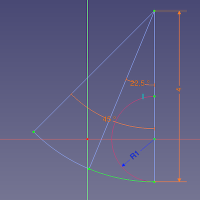
Intermediate sketch showing the DynamicRadius of the hinge arc of 4 (mm) at a given angle of 45° (and the half arc for output)
Film hinge sketch
This sketch defines the thickness and the adjacent geometry of the film hinge. Therefore we load the half arc of the intermediate sketch as external geometry to use it as the base for the film part. (a fraction of 180° in this case)
This film hinge is intended to keep the connected parts touching each other when closed. This can be achieved by calculating a circular arc of the needed length then create a strip with constant thickness and finally apply fillets where the strip meets the object halves. The last step somehow shortens the loop, but in the real world this is not a problem, because the arc will never be circular and so the fillets have an influence on the arc's curvature but not on its functionality.

Hinge sketch showing the outline of the hinge based on the external geometry from the half arc of the intermediate sketch


![]()

Half hinge with selected mirror plane → ![]() mirrored film hinge
mirrored film hinge
Hint: ![]() Part Mirror only accepts the three basic planes and so can not be used in such a case.
Part Mirror only accepts the three basic planes and so can not be used in such a case.
- (In retrospect it was a wise decision to start this example with the combination of PartDesign and Sketcher.)
Finally two parameters define the size of the film hinge:
- the NeutralRadius of the basic sketch
- the thickness value of the film hinge sketch
Bending the film hinge
The bend angle is controlled by the constraint ArcAngle of the intermediate sketch and can be altered in its Property View.
But we are proper designers and have named our sketches constraints and dimensions properly and so can address the controlling angle via Python.
Some basic lines of code to be embedded in a GUI context could look like this:
doc=App.ActiveDocument
sketch=doc.getObjectsByLabel('IntermediateSketch')[0]
 ...
sketch.getDatum('ArcAngle')
 ...
sketch.setDatum('ArcAngle',App.Units.Quantity('50.000000 deg'))
doc.recompute(None,True,True)
A short explanation:
doc = App.ActiveDocument: To address the active document by an alias called docsketch = doc.getObjectsByLabel('IntermediateSketch')[0]: To address the relevant sketch by the alias sketch.- The method getObjectsByLabel() returns a list of objects and we have to suffix index
0to pick the first object in the list. (We do not expect any other object having the same label and so do not have to care about other items in the list.)
- The method getObjectsByLabel() returns a list of objects and we have to suffix index
sketch.getDatum('ArcAngle'): Returns the current value of the dimensional constraint ArcAngle (to the Report view)sketch.setDatum('ArcAngle', App.Units.Quantity('50.0 deg')): Sets the value of ArcAngle to50°doc.recompute(None,True,True): To update the whole document to show the changes of dependant geometry as well.
Connecting geometry
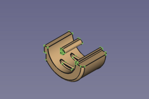
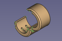
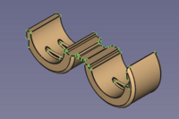
Two halves of a clip stuff are waiting to get attached to the hinge, one on the static side and one on the movable side.

Two halves of a simple clip
The static side is easy:
- Activate the body and adjust the position and orientation properties in the properties editor until it matches with the film hinge.
- Activate the hinge body.
- Select the
 PartDesign Boolean tool with the (default) Fuse option.
 - In the dialog press the Add body button.
- select the body of the static half of the clip.
- Press OK to finish and close the dialog.
![]()

Film hinge and static half in modelling position → film hinge with relocated and ![]() fused static half
fused static half
But the moving side is different: The related half of the clip geometry has to move into the right position before a (re-) calculation of a Fuse operation gets started.
At this point I'm missing an "Attachment with offset" function like that of Assembly3 to attach the clip geometry to one of the moving faces. But after a bit of experimenting and tweaking I found out:
 Std Part and
  PartDesign Body containers are not supported by
  Part Attachment.
- While it is possible to use Attachment to align them, the attachment won't be parametrically linked.
- Attachment can be applied to a PartDesign feature. This and features depending on it are repositioned according to the base geometry. But!:
- Independent PartDesign features won't move and so it will change the resulting shape and break it in the end.
- We are advised to keep features independent to avoid impacts due to the Topological naming problem.
 PartDesign Clone creates a body with a single feature that can be use with Attachment.
With that in mind, a workflow could look like this:
- Select the body of the movable half.
- Use the Clone command.
- In the new body select the Clone object in the Tree View.
- Use the Part Attachment tool to add attachment properties to the Clone object.
- The Attachment dialog opens.
- Select a vertex for the origin.
- Select an edge for the first direction.
- Select an edge for the second direction.
- Probe the attachment modes to find the best fitting one.
- Tweak rotation and coordinate values until until the geometry is in modelling position again.
- Press OK to close the dialog.
- With the hinge body still active select the PartDesign Boolean tool.
- In the dialog press the Add body button.
- select the body of the movable half .
- Press OK to finish and close the dialog.

The movable half will be ![]() attached to a corner of the movable hinge side (Map Mode OXZ: vertex, edge, edge)
attached to a corner of the movable hinge side (Map Mode OXZ: vertex, edge, edge)
In retrospect it would have been wiser to provide the attachment geometry with the IntermediateSketch to avoid another source of the Topological naming problem.
![]()

The clip so far and the movable half in modelling position → finished clip with ![]() attached and
attached and ![]() fused movable half
fused movable half
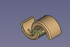
Now the result should be a single solid clip, that can be closed and opened by changing the ArcAngle of the film hinge. Allowed angles: 0.1° to 180°, the film section must not get straight, and more than closed doesn't make sense. (At 180° the object may get fused at tangent or overlapping areas, but a little extra gap could help if that is not acceptable.)

![]()
![]()
Clip almost closed → Clip half closed → Clip in mould condition
Tato stránka je načtena z https://wiki.freecad.org/Sketcher_Examples