|
|
| Menu location |
|---|
| Part → Attachment |
| Workbenches |
| Part, PartDesign |
| Default shortcut |
| None |
| Introduced in version |
| 0.17 |
| See also |
| Placement, Basic Attachment Tutorial |
Popis
The ![]() Part EditAttachment command attaches an object to one or more other objects. The attached object is linked to the referenced object(s), which means that if the placement or geometry of the referenced object(s) is changed, the placement of the attached object will update accordingly.
Part EditAttachment command attaches an object to one or more other objects. The attached object is linked to the referenced object(s), which means that if the placement or geometry of the referenced object(s) is changed, the placement of the attached object will update accordingly.
Attacher engines
The attachment of an object is controlled by one of four attacher engines. The default engine that is used for an object depends on its type. An object's attacher engine can be changed via its ÚdajeAttacher Engine property (introduced in 1.0) or its hidden ÚdajeAttacher Type property.
The available engines are listed in the table below. Attacher engines control the ÚdajePlacement of objects. All engines can be used for all objects that have this property. But the results of the last three make the most sense if the shape of the object matches the mentioned 'Logical Shape'.
| Attacher Engine | Attacher Type | Logical Shape |
|---|---|---|
| Engine 3D | Attacher::AttachEngine3D | |
| Engine Plane | Attacher::AttachEnginePlane | Planar face coincident with the XY-plane of the Placement |
| Engine Line | Attacher::AttachEngineLine | Straight edge collinear with the Z-axis of the Placement |
| Engine Point | Attacher::AttachEnginePoint | Vertex coincident with the origin of the Placement |
The rest of this page focuses on the Engine 3D. The modes of the other engines are only listed. Note that the modes of Engine Plane are in fact identical to those of Engine 3D.
Usage
- Select the object to be attached.
- Do one of the following:
- If the object already has a ÚdajeMap Mode property: click in that field in the Property View and press the … button that appears.
- Select the Part →
 Attachment option from the menu.
- The Attachment task panel opens.
- At the top of the task panel Not attached can be read. The first button labeled Selecting… is highlighted to indicate a selection in the 3D View is expected.
- Select a vertex, edge or face/plane belonging to another object.
- In the input field to the right of the button, the referenced object and subelement are shown. For example, if a face of a Part Box is selected, the field may show
Box:Face6. The label of the button displays the subelement type now. - The available modes are filtered based on the selected references and their order. For example, for modes Align O-Z-X to Align O-Y-X the first reference must be a vertex. If the first reference is a subelement of a different type, they are removed from the list.
- Attached with mode <description> is now displayed at the top of the task panel.
- Optionally select a different Attachment Mode from the list. For information on the attachment modes, hover the mouse over them for a tooltip to appear.
- Depending on the selected mode, add up to three more references by pressing the Reference2, Reference3, and Reference4 buttons and repeating step 5. It is also possible to specify all references before selecting an attachment mode.
- Optionally set an Attachment Offset.
- Press OK.
- If applicable, optionally change the ÚdajeMap Path Parameter property in the Property View.
Attachment modes
Engine 3D
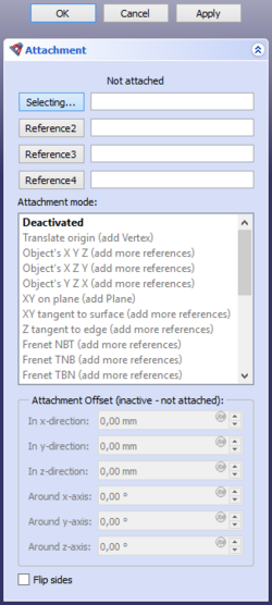
Deactivated
Attachment is disabled. The object can be moved by editing its Placement property.
Translate origin
The origin is matched with a vertex. The orientation is still controlled by the Placement property of the attached object.
- Reference combinations
- Vertex.
Object's X Y Z
The Placement is made equal to the Placement of a linked object.
- Reference combinations
- Any
- Conic
Object's X Z Y
The X, Y and Z axes are matched with a linked object's local X, Z and -Y axes, respectively.
- Reference combinations
- Any
- Conic
Object's Y Z X
The X, Y and Z axes are matched with a linked object's local Y, Z and X axes, respectively.
- Reference combinations
- Any
- Conic
XY on plane
The XY-plane is aligned to coincide with a planar face.
- Reference combinations
- Plane
XY tangent to surface
The XY-plane is made tangent to a face at a vertex.
- Reference combinations
- Face, Vertex
- Vertex, Face
Z tangent to edge
The Z-axis is aligned to be tangent to an edge. An optional vertex defines where.
If no vertex is linked the ÚdajeMap Path Parameter property determines the point.
- Reference combinations
- Edge
- Edge, Vertex
- Vertex, Edge
Frenet NBT
The X and Y axes are aligned to the normal (N) and binormal (B) axes of the Frenet-Serret coordinate system at a point on a curved edge. An optional vertex defines where.
If no vertex is linked the ÚdajeMap Path Parameter property determines the point. The object's origin is translated to the vertex if the vertex is first, or kept at the curve if the curve is first.
Frenet NBT is similar to Z tangent to edge, except that the X-axis is well-defined.
- Reference combinations
- Curve
- Curve, Vertex
- Vertex, Curve
Frenet TNB
The X and Y axes are aligned to the tangent (T) and normal (N) axes of the Frenet-Serret coordinate system at a point on a curved edge. An optional vertex defines where.
See Frenet NBT.
Frenet TBN
The X and Y axes are aligned to the tangent (T) and binormal (B) axes of the Frenet-Serret coordinate system at a point on a curved edge. An optional vertex defines where.
See Frenet NBT.
Concentric
The XY-plane is aligned to the osculating circle at a point on an edge. An optional vertex defines where.
If no vertex is linked the ÚdajeMap Path Parameter property determines the point.
- Reference combinations
- Curve
- Circle
- Curve, Vertex
- Circle, Vertex
- Vertex, Curve
- Vertex, Circle
Revolution Section
The Y-axis is aligned to match the axis of the osculating circle at a point on an edge. An optional vertex defines where.
See Concentric.
XY-plane by 3 points
The XY-plane is aligned to pass through three vertices. The X-axis will pass through the first two vertices.
- Reference combinations
- Vertex, Vertex, Vertex
- Line, Vertex
- Vertex, Line
- Line, Line
XZ-plane by 3 points
The XZ-plane is aligned to pass through three vertices. The X-axis will pass through the first two vertices.
See XY-plane by 3 points.
Folding
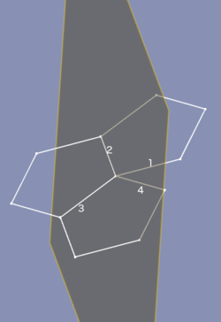
This is a special mode for folding polyhedra. Select four lines that share a common point in this order: contour line (1), fold line (2), other fold line (3), other contour line (4). To determine the coordinate system the selected contour lines are made coincident by rotating line 1 around line 2, and line 4 around line 3. The origin is matched with the common point, the X-axis is matched with line 2, the Y-axis is aligned towards the direction of the coincident contour lines.
- Reference combinations
- Line, Line, Line, Line
Inertia CS
The X, Y and Z axes are matched with those of an inertial coordinate system, constructed on principal axes of inertia and center of mass.
- Reference combinations
- Any
- Any, Any
- Any, Any, Any
- Any, Any, Any, Any
Align O-Z-X
The origin is matched with the first vertex. The Z and X axes are aligned towards a vertex or along a line.
See Align O-X-Y Type Attachment Modes for more details.
- Reference combinations
- Vertex, Vertex, Vertex
- Vertex, Vertex, Line
- Vertex, Line, Vertex
- Vertex, Line, Line
- Vertex, Vertex
- Vertex, Line
Align O-Z-Y
The origin is matched with the first vertex. The Z and Y axes are aligned towards a vertex or along a line.
See Align O-Z-X.
Align O-X-Y
The origin is matched with the first vertex. The X and Y axes are aligned towards a vertex or along a line.
See Align O-Z-X.
Align O-X-Z
The origin is matched with the first vertex. The X and Z axes are aligned towards a vertex or along a line.
See Align O-Z-X.
Align O-Y-Z
The origin is matched with the first vertex. The Y and Z axes are aligned towards a vertex or along a line.
See Align O-Z-X.
Align O-Y-X
The origin is matched with the first vertex. The Y and X axes are aligned towards a vertex or along a line.
See Align O-Z-X.
XY parallel to plane
The XY-plane is aligned to be plane-parallel to the XY-plane of the Placement of a linked object, and pass through a vertex. The origin is matched with the projection of the origin of the linked object onto the XY-plane.
Note that you have to select a whole object and not a subelement such as a face or plane.
- Reference combinations
- Any whole object (with a ÚdajePlacement property), Vertex
Engine Plane
- Deactivated
- Translate origin
- Object's XY
- Object's XZ
- Object's YZ
- Plane face
- Tangent to surface
- Normal to edge
- Frenet NB
- Frenet TN
- Frenet TB
- Concentric
- Revolution Section
- Plane by 3 points
- Normal to 3 points
- Folding
- Inertia 2-3
- Align O-N-X
- Align O-N-Y
- Align O-X-Y
- Align O-X-N
- Align O-Y-N
- Align O-Y-X
- XY parallel to plane introduced in 1.0
Engine Line
- Deactivated
- Object's X
- Object's Y
- Object's Z
- Axis of curvature
- Directrix1
- Directrix2
- Asymptote1
- Asymptote2
- Tangent
- Normal to edge
- Binormal
- Through two points
- Intersection introduced in 1.0
- Proximity line
- 1st principal axis
- 2nd principal axis
- 3rd principal axis
- Normal to surface
Engine Point
- Deactivated
- Object's origin
- Focus1
- Focus2
- On edge
- Center of curvature
- Center of mass
- Vertex
- Proximity point 1
- Proximity point 2
Attachment offset
Attachment Offset becomes active when an attachment mode other than Deactivated has been selected. It is used to apply a linear or rotary offset within the attachment coordinate system (ACS), as defined by the attachment mode and the referenced object(s).
- In x-direction: sets an offset distance along the X-axis of the ACS.
- In y-direction: sets an offset distance along the Y-axis of the ACS.
- In z-direction: sets an offset distance along the Z-axis of the ACS.
- Around x-axis: rotates the attached object around the X-axis of the ACS.
- Around y-axis: rotates the attached object around the Y-axis of the ACS.
- Around z-axis: rotates the attached object around the Z-axis of the ACS.
- Flip sides: if checked, the attachment is reversed. This is equivalent to rotating the object 180° around the Y-axis of the ACS.
Limitations
- If selecting two lines results in an error: "Points are collinear. Can't make a plane", try selecting three vertices instead [1].
Tato stránka je načtena z https://wiki.freecad.org/Part_EditAttachment