Эта документация не закончена. Пожалуйста, помогите и внесите свой вклад в разработку документации.
Пример документирования команды Gui объясняет, как должны быть задокументированы команды. Просмотрите Category:UnfinishedDocu/ru, чтобы увидеть больше незавершённых страниц, подобных этой. Смотрите Category:Command Reference/ru для всех команд.
Смотрите Wiki Страницы, чтобы узнать о редактировании вики-страниц, и зайдите на страницу Помоги FreeCAD, чтобы узнать о других способах, которыми вы можете внести свой вклад.
Введение
![]() SheetMetal — это внешний верстак, не входящий в стандартную установку FreeCAD. Он был разработан для создания и развертывания объектов из листового металла.
SheetMetal — это внешний верстак, не входящий в стандартную установку FreeCAD. Он был разработан для создания и развертывания объектов из листового металла.
Характеристики изделий из листового металла:
- Они имеют постоянную толщину
- Они могут быть развернуты, если состоят только из плоских стенок и цилиндрических соединений
Инструмент развертывания в обеих версиях не ограничивается деталями, изготовленными с помощью инструментов этого верстака, он может обрабатывать также объекты верстаков Part и PartDesign, если они соответствуют указанным выше характеристикам.
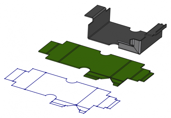
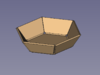
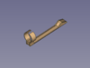
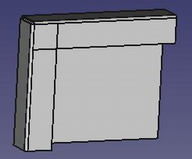
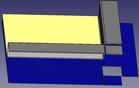
Вверху: модель из листового металла, созданная с помощью дополнения SheetMetal
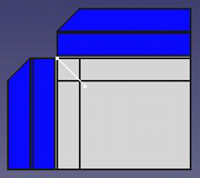
В центре: развернутый объект
Снизу: эскиз развертки с линиями изгиба для экспорта в DXF.
Если экспорт в формате DXF используется для управления станками (например, лазерной резкой), необходимо изменить файл DXF, удалив линии, отображающие сгибы, поскольку эти линии станок может использовать для резки.
Установка
Этот верстак можно установить из Менеджер дополнений. Для ручной установки смотрите Установка дополнительных верстаков.
Инструменты
The Sheet Metal tools are all located in the Sheet Metal menu and the Sheet Metal toolbar that appear when you load the SheetMetal Workbench.
 Add base shape: Adds a basic sheet metal object from parameters.
 New Sketch: Creates a new sketch without switching workbenches (introduced in version 0.7.61). It invokes either the Sketcher NewSketch tool, or the PartDesign NewSketch tool if a PartDesign Body is active.
 Make Base Wall: Creates a sheet metal base object from a sketch, either a profile or a plate.
 Convert to Sheet Metal: Converts a solid or shell to a sheet metal object (introduced in version 0.8.0).
 Make Wall: Adds a flange on each selected edge of a base plate. (The flange can be turned into a hem by modifying its angle.)
 Make Hem: Adds a hem on each selected edge of a base plate. (Similar to the above tool but with settings optimized for hem creation. - introduced in version 0.8.10)
 Extend Face: Extends a sheet metal plate at a selected edge face along its normal.
 Extend by Sketch: Extends a sheet metal plate at a selected edge face by adding an outline sketch. It can be used to create interlocking geometry. (This was split from the above tool and is available in version 0.7.57 and newer)
 Fold a Wall: Folds a face at a chosen line with a specified bend radius.
 Unfold: Flattens a folded sheet metal object and generates an unfold solid and an outline sketch with bend lines (provides a dialog to set parameters).
 Unattended Unfold: Flattens a folded sheet metal object and generates an unfold solid and an outline sketch with bend lines (if parameters have already been set).
 Unfold Update: Updates all unfold objects.
 Add Corner Relief: Adds a corner relief to a corner.
 Make Relief: 1st step to convert a shell object into an unfoldable sheet metal object, adds a relief (cutout) to a corner.
 Make Junction: 2nd step to convert a shell object into an unfoldable sheet metal object, creates an open junction on the edge of two walls.
 Make Bend: 3rd step to convert a shell object into an unfoldable sheet metal object, replaces sharp edges with round bends.
 Wrap Cutout: Cuts a sketch based hole pattern along the folded walls of a sheet metal object.
 Extruded Cutout: Creates an extruded cutout from a sketch extrusion.
 Make Forming in Wall: Embosses shapes with or without holes into a sheet metal plate.
Brief description
This workbench provides tools for the two main tasks:
- Create sheet metal objects
- Unfold sheet metal objects
This section is meant to give a rough idea of how to use the supplied tools. More detailed information can be found on each tool's own page (see above) or in the linked tutorials (see below).
Create a sheet metal object
Start with a profile
- Create an open polyline (preferably with the Sketcher Workbench)
- Use the Make Base Wall command to create a sheet metal profile.
Start with a blank
- Create a closed polyline (preferably with the sketcher)
- Use the Make Base Wall command to create a sheet metal blank.
Start with a base shape
- Use the Add base shape comand to add a basic sheet metal object from parameters.
Start with a solid shape
Alternatively a blank and a profile shape can be created with tools of the ![]() Part Workbench or
Part Workbench or ![]() PartDesign Workbench.
PartDesign Workbench.
- Part Workbench:
- Create a
 Part Extrude from a closed 2D wire such as a
  Draft Rectangle, a
  Draft Wire, or a Sketch.
- Depending on the 2D wire shape and the extrusion length this creates a blank or a profile.
- Create a
- PartDesign Workbench:
- Create a
 PartDesign Body
 - Create a closed Sketch.
- Create a
 PartDesign Pad from the sketch.
- Depending on the sketch shape and pad height this creates a blank or a profile.
- Create a
Already folded shapes require hollow shapes to be transformed into unfoldable sheet metal shapes by adding some gaps or connections between their walls:
- Create a hollow shape:
- Create a Part Extrude as above, or use a primitive like a
 Part Box instead.
 - Use
 Part Thickness to obtain a hollow shape of constant thickness.
- Create a PartDesign Pad as above, or use a primitive like a
 PartDesign AdditiveBox.
 - Use
 PartDesign Thickness to obtain a hollow shape of constant thickness.
- Create a
- Adding gaps and connections to the edged shape:
- Use Make Relief to cut off selected corners.
- Use Make Junction to create junctions with gaps between adjoining walls that need to be disjoined.
- Use Make Bend to create cylindrical connections for the remaining walls that need to stay joined.
- Use
- Check if the resulting sheet metal object can be unfolded. (see Unfold... below).
If you start modeling a sheet metal shape in a ![]() PartDesign Body, you can mix SheetMetal features with PartDesign features such as
PartDesign Body, you can mix SheetMetal features with PartDesign features such as ![]() PartDesign Pocket or
PartDesign Pocket or ![]() PartDesign Hole.
PartDesign Hole.
Adding more features
The unfoldable basic sheet metal shape can be extended:
- Use Extend Face to enlarge walls.
- Use Extend by Sketch to partially extend walls and optionally create interlocking geometry. (V0.7.57 and above)
- Use Make Wall to add new flanges or hems to the existing shape.
- Use Add Corner Relief to add or reshape corner reliefs.
- Use Fold a Wall to fold a wall at a chosen line, i.e. it will trimm a wall at said line, relocate the cut away side, and rejoin them with a cylindrical connection.
- Use Sketch on Sheet metal to cut holes into the shape starting on a chosen wall and then following the adjoined walls and connections.
- Use Extruded Cutout to cut oblique holes but obtain perpendicular edge faces that do not prevent the shape from being unfolded.
- Use Make Forming in Wall to stamp a shape into a plate (wall).
- After the creation of a WallForming feature the SheetMetal object is no longer unfoldable!
Some parameters will be inherited from the parent object(s) but it is better to check the relevant parameters at each stage.
Several tools from other workbenches can be used to add holes or to reshape edges.
Unfold a sheet metal object
To unfold a sheet metal object activate the ![]() Unfold or the
Unfold or the ![]() Unattended Unfold tool.
Unattended Unfold tool.
The result will be a 3D object with an optional outline sketch including bend lines.
Examples
Until tutorial pages are available on this wiki there is an Examples page.
It contains some hints about properties as well.
Ограничения
- The workbench is affected by the topological naming issue that is inherent to FreeCAD. If an edit of a bend earlier in the history of the part renumbers the faces, then the following bends may be affected and switch faces. If the bend features do not break, you can double-click on it to get a dialog where you can select the proper face in the 3D View, and update the Bend.
- The Unfold tool has some limitations, and will fail in certain complex situations. When it fails, try to select a different face.
- Frequent case of crash: take a lot of precautions not to cut in the hinges (the folds) either along the faces or in the angles nor to make holes or notches through the angles.
Tutorials
SheetMetal Tutorial by meme2704
The following tutorial is reproduced from the PDF tutorial mentioned in Links.
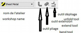
Presentation of the workbench
After downloading the extension and install, open it.
1st operation
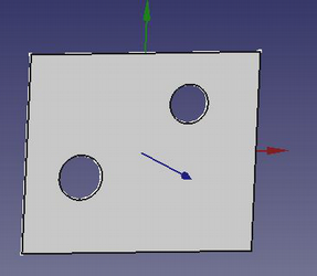
- Get the base: use either the workbenches "part" or "draft", make 1 sketch that will contain all holes and any cuts, extrude this base to the thickness of the sheet.
- Bear in mind that the edges will always be in addition as well as the folding radii.
2nd operation
- Open the SheetMetal workbench.
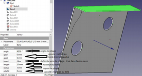
- Select 1 thickness of the edge (edge) of the base plate and click on the "bend" tool 90° default bend angle can be changed from 0 to 90°.
- Edge height is 10mm by default, editable from 0.1 to xxxmm.
- Bending radius is by default equal to thickness, editable from 0.1 to xxmm (never put 0).
- Gap1, gap2 is the withdrawal of the folded edge from the corner of the base (0 accept).
- Invert default: false folds to Z +, true to ZReliefd cuts the corner between the fold and the base (inactive if gap = 0).
- Reliefw adds 1 slot between the crop and the edge (inactive if reliefd = 0).
Repeat as many times as there are sides to bend.
Folding 1 return with use of "extend".
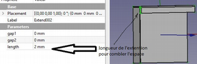
To add 1 back repeat the same operation by selecting the thickness of the concerned edge.
To reduce the space between the 2 edges, use "extends".
Select the thickness and specify the length to add.
Note that if the extension of the 1st edge is made before the fold of the return, it will not be taken into account, if 1 identical fold is added to the extension, it will appear correct but the unfolding will not be done.
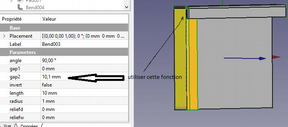
Folding of 1 2nd edge:
Now we must separate the 2 edges otherwise they will merge and unfolding will be impossible.
- 1st method: make 1 withdrawal of 1 edge.
- Give 1 value slightly greater than gap1 (or gap2), at zero there is still fusion.
- 2nd method make 1 cut at 45 ° see further, use this tool.
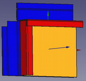
Unfolding
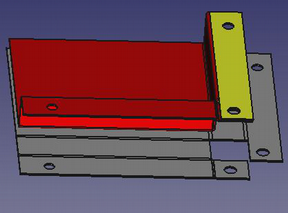
Choose 1 reference face (here the orange face) and click on the button in the toolbar.
We obtain the blue part of which it is enough to modify the values X, Y, or Z to see it in totality.
Cut the flaps at 45°
After folding the flaps without having made a withdrawal, the shape thus appears.
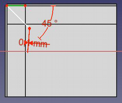
To do it must split at 45 ° (or following the bisector flaps are unequal width).
- Create 1 new skit related to the common part of the 2 flaps.
- Create 1 linked stop by selecting the outer edge of the "hinge".
- Draw 1 triangle whose top is constrained at the end, oriented 1 side at 45 °, give the small side 1 minimum width (0.1mm is enough), and make 1 pocket.
Be careful not to scratch the "hinge" where the nakedness of bound the tip of the triangle at the edge of the fold line.
Unfolding
Piercing edges and flaps
Make these holes and cuts after folding and before unfolding.
Always take care not to "scratch" the fold lines.
Make wired flaps
Make 1 fold on the edge of the side, at 45 ° of 0.1mm long, then 1 other reverse at 45 ° of the length of the contiguous flap, then extend the opposite side, it will pass over and they will not be merged.
Special case of this same pierced edge
In this particular case, unfolding only works by choosing the yellow face as a reference.
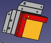
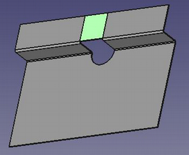
Special case hole straddling the folds
Previously it is said several times that it is not necessary to cut the folding lines.
How to do ?
- Make the base with its half-round hole and make the 2 half-sided and the 2 half-folds separately.
- Then make 1 extension on 1 of the sides of the width of the opening minus 0.1mm, the 2 edges thus remain separated.
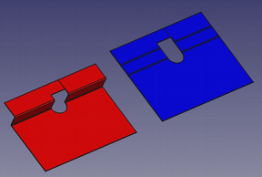
- Then on this extension (in green) draw the contour of the cut and make 1 pocket
- The result is the red piece above, and the unfolding works, stays the line that separated the 2 edges previously
Videos
- The Elegant SheetMetal Workbench by Joko Engineering
Ссылки
- Macro Sheet Metal Unfolder, the original macro the Unfold tool is based on.
- An English and French tutorial in PDF format on the FreeCAD forum.
- Report bugs/Request features: https://github.com/shaise/FreeCAD_SheetMetal/issues.
References
- Author:
- Folding tools: Copyright 2015-2018 by Shai Seger
- Unfolding tool: Copyright 2014 by Ulrich Brammer
- License: GPLv3
- Source code on github: https://github.com/shaise/FreeCAD_SheetMetal
Эта страница получена от https://wiki.freecad.org/SheetMetal_Workbench