This documentation is not finished. Please help and contribute documentation.
GuiCommand model explains how commands should be documented. Browse Category:UnfinishedDocu to see more incomplete pages like this one. See Category:Command Reference for all commands.
See WikiPages to learn about editing the wiki pages, and go to Help FreeCAD to learn about other ways in which you can contribute.
|
|
| Menu location |
|---|
| SheetMetal → Fold a Wall |
| Workbenches |
| SheetMetal |
| Default shortcut |
| C F |
| Introduced in version |
| - |
| See also |
| None |
Description
The ![]() SheetMetal AddFoldWall command folds a sheet metal plate (blank) at a chosen line.
SheetMetal AddFoldWall command folds a sheet metal plate (blank) at a chosen line.
It can be used with a pre-cut blank to
- create a perforated bend zone
- leave planar sections within the bend area and beyond e.g. tabs. (needs gaps in the bend line)
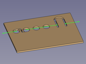
![]()
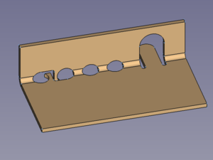
Pre-cut blank and bend line with two gaps → perforated bend zone with some still planar geometry
Usage
- (Prepare a
 sketch for the bend line (segments) on the face to be bent)
- Select the face to be bent.
- Press Ctrl and select the sketch containing the bend line (segments) (preferably in the tTree View) to add it to the selection.
- There are several ways to invoke the command:
- Press the
 Fold a Wall button.
 - Select the Sheet Metal → Fold a Wall option from the menu.
- Right-click in the Tree View or the 3D View and select the Sheet Metal → Fold a Wall option from the context menu.
- Use the keyboard shortcut: C Then F.
- Press the
- A Fold object is created and the Fold on sketch line properties Task Panel opens:
- Optionally press the Base Object button and select a different face.
- Optionally press the Bend Line button and select a different sketch.
- Optionally adjust the parameters in the Task Panel.
- Press the OK button to finish the command and close the Task Panel.
- Optionally adjust the parameters in the Property View.
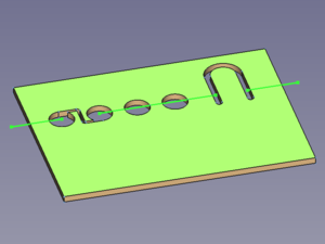
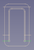
![]()
The bend line(s) lying in the middle of the perforation → to keep the bend centred the same way the property DataPosition has to be set to middle
Task Panel
A task panel was introduced in version 0.5.00
Double-click an existing Fold object in the Tree View to re-open the task panel and edit the parameters.

- Base Object: Links a different Sketch to the base Object property.
- Bend Line: Links a different Sketch to the Bend Line property.
- Flip Direction: Toggles the Invert Bend property.
- Unbend: Toggles the Unfold property.
- Bend Radius: Sets the radius property.
- Bend Angle: Sets the angle property.
Notes
- The bend line sketch has to be coplanar to the selected face.
- The bend line segments have to be colinear to each other.
Properties
See also: Property View.
A SheetMetal Fold object is derived from a Part Feature object or, if it is inside a PartDesign Body, from a PartDesign Feature object, and inherits all its properties. It also has the following additional properties:
Data
Parameters
- DataBend Line (
Link): "Bend Reference Line List". Links to the bend line objects. - DataPosition (
Enumeration): "Bend Line Position".intersection of planes(introduced in version 0.4.12),forward(default),middle,backward.
- Dataangle (
Angle): "Bend Angle". Default angle:90,00°. - Database Object (
LinkSub): "Base Object". Link to the planar face to be bent. - Datainvert (
Bool): "Invert Bend Direction". Default:false - Datainvertbend (
Bool): "Invert Solid Bend Direction". Default:falsetrueswaps the side of the line to be bent.
- Datakfactor (
FloatConstraint): "Neutral Axis Position". Default:0,50. - Dataradius (
Length): "Bend Radius". Default:1,00 mm. - Dataunfold (
Bool): "Unfold Bend". Default:false
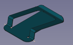
Example
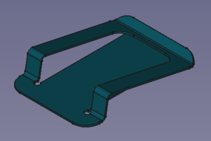
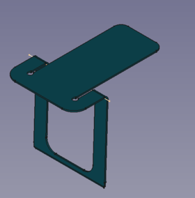
A simple clip
Preparation
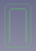
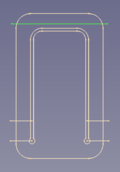
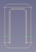
This clip is made of a blank that receives three folds and so we need four sketches prepared in advance:
- - one for the outline plus slot (blank)
- - one for the bend at the tip
- - one for the upward bend
- - one for the downward bend
Easiest way to guarantee that one face of the blank and all folding lines are coplanar is to create all sketches on the same plane - the XY_Plane in this case.
The folding lines could be created with other tools but hey, we have a ![]() Sketcher!
Sketcher!
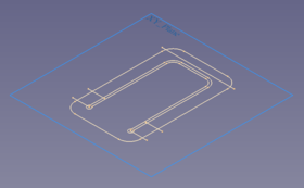
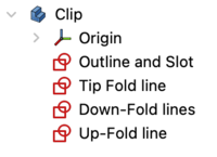
Sketches on their common plane and their representation in the model tree
Workflow
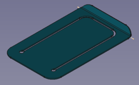
- Create a blank
- Select the outline sketch
- Press the
 Make Base Wall button
or use the keyboard shortcut: C then B
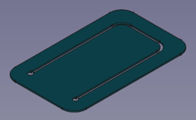
(The blank is padded in z direction and so it has to be flipped
each time, to select the bottom face that is lying on the sketch plane)
- Fold the tip
- Select the blank's bottom face
- Select the sketch named Tip Fold line (preferably from the Tree View)
(and don't forget the control/command key ) - Press the Fold a wall button
or use the keyboard shortcut: C then F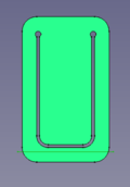
- The fold should be 90° down and so some values in the properties window need to be set e.g.:
- the angle value to 60°
- the invert value to true for an upward bend
- Create the downward fold
- Select the blank's bottom face
- And then the sketch named Down-Fold line
- Press the Fold a wall button
or use the keyboard shortcut: C then F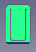
- Set the angle value to 92°
- If the wrong section of the part moved set the invertbend value to true
- To create the upward fold
- select the blank's bottom face
- and then the sketch named Up-Fold line
- Press the Fold a wall button
or use the keyboard shortcut: C then F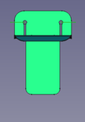
- Set the angle value to 80°
- If the fold is downward set the invert value to true
- If needed set the invertbend value to true
Done!
Note!: In real life the upward fold must be done before the downward fold. Only the virtual world of CAD allows us to bend through solid material. This way the orientation of the static section doesn't change.
All sketches lie on the same plane to avoid sketches attached to moveable faces.
This page is retrieved from https://wiki.freecad.org/SheetMetal_AddFoldWall