|
|
| Ubicación en el Menú |
|---|
| Croquis -> Polilínea |
| Entornos de trabajo |
| Croquis, Arquitectura |
| Atajo de teclado por defecto |
| P L |
| Introducido en versión |
| 0.7 |
| Ver también |
| Línea Boceto, BSpline Boceto |
Description
Descripción
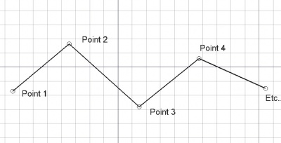
La herramienta Contorno crea polilíneas (secuencias de líneas formadas por varios segmentos) en el plano de trabajo actual. Toma el Espesor de línea y color previamente definidos en la pestaña de tareas. La herramienta Contorno se comporta como la herramienta Línea, con la excepción de que no termina tras indicar dos puntos.
The corners of a Draft Wire can be filleted (rounded) or chamfered by changing its DatosFillet Radius property or DatosChamfer Size property respectively. It is also possible to subdivide the edges of a Draft Wire by changing its DatosSubdivisions property.
Create
Usage
See also: Draft Tray, Draft Snap and Draft Constrain.
Utilización
- Presiona el botón
 Contorno, o presiona las teclas W y I
 - Selecciona un primer punto en la vista 3D, o escribe unas coordenadas
- Selecciona puntos adicionales en la vista 3D, o escribe coordenadas
- Presiona F o C, o haz doble clic en el último punto, o selecciona el primer punto para terminar o cerrar el contorno. Si el contorno es cerrado, también será una cara, aunque su apariencia sea alámbrica.
Options
The single character keyboard shortcuts available in the task panel can be changed. See Draft Preferences. The shortcuts mentioned here are the default shortcuts.
Opciones
- Si se seleccionan Draft Lineas conectadas al presionar el botón Draft Wire, se convertirán en un Wire y el comando terminara. introduced in 0.17
- Presiona F o el botón
 Terminar para finalizar el contorno, dejándolo abierto
 - Presiona C o el botón
 Cerrar o selecciona el primer punto para finalizar el contorno, pero haciendo que se cierre añadiendo un último segmento entre el último punto y el primero.
 - Presiona X, Y o Z después de un punto para restringir el siguiente punto con respecto al eje dado.
- Para introducir coordenadas manualmente, simplemente introduce los números, presiona ENTER entre cada componente X, Y y Z.
- Presiona R o selecciona la casilla para activar / desactivar el modo Relativo. Si está activado el modo relativo, las coordenadas del siguiente punto son relativas al anterior. En caso contrario, son absolutas, desde el origen de coordenadas (0,0,0).
- Presiona T o selecciona la casilla para activar / desactivar el modo Continuo. Si está activado el modo continuo, la herramienta Contorno se iniciará después de que termines o cierres el contorno actual, permitiendo que dibujes otro contorno sin necesidad de pulsar el botón de Contorno otra vez.
- Presiona CTRL mientras dibujas para forzar el ajuste del punto a la ubicación de ajuste más cercana, independientemente de la distancia.
- Presiona SHIFT mientras dibujas para restringir tu siguiente punto horizontal o verticalmente en relación al último punto indicado.
- Presiona W o el botón
 Contorno para eliminar el segmento existente y comenzar el contorno desde el último punto.
 - Presiona CTRL+Z o el botón
 Deshacer para deshacer el último punto.
 - Presiona I o el botón Relleno para que el Wire se muestre como una cara si esta cerrada.
- Presiona ESC o el botón Cancelar para abortar el comando Línea actual.
- Los Wires cerrados, cuando están en el modo de visualización "Líneas planas", pueden mostrar un patrón de sombreado, configurando a continuación la propiedad "Patrón".
Join
Usage
- The end points of the Draft Lines and/or Draft Wires to be joined must be exactly coincident. If required first adjust points to ensure that this is the case.
- Select two or more Draft Lines and/or Draft Wires.
- There are several ways to invoke the command:
- Press the
 Draft Wire button.
 - Select the Drafting → Polyline option from the menu.
- Use the keyboard shortcut: P then L.
- Press the
Notes
- A Draft Wire can be edited with the Draft Edit command.
- A Draft Wire can be converted to a Draft BSpline with the Draft WireToBSpline command.
- Draft Lines and Draft Wires can also be joined with the Draft Join command or the Draft Upgrade command.
Properties
See also: Property View.
A Draft Wire object is derived from a Part Part2DObject1.0 and below or a Part Feature object1.1 and above and inherits all its properties. It also has the following additional properties:
Data
Attachment
The object has the same attachment properties as a Part Part2DObject.
Draft
- DatosArea (
Area): (read-only) specifies the area of the face of the wire. The value will be0.0if DatosMake Face isfalseor the face cannot be created. - DatosBase (
Link) - DatosChamfer Size (
Length): specifies the length of the chamfers at the corners of the wire. - DatosClosed (
Bool): specifies if the wire is closed or not. If the wire is initially open this value isfalse, setting it totruewill draw a line segment to close the wire. If the wire is initially closed this value istrue, setting it tofalsewill remove the last line segment and make the wire open. - DatosEnd (
VectorDistance): specifies the end point of the wire. - DatosFillet Radius (
Length): specifies the radius of the fillets at the corners of the wire. - DatosLength (
Length): (read-only) specifies the total length of the wire. - DatosMake Face (
Bool): specifies if the wire makes a face or not. If it istruea face is created, otherwise only the edges are considered part of the object. This property only works if DatosClosed istrueand if the wire does not self-intersect. - DatosPoints (
VectorList): specifies the points of the wire in its local coordinate system. - DatosStart (
VectorDistance): specifies the start point of the wire. - DatosSubdivisions (
Integer): specifies the number of subdivisions for each edge of the wire. If it is1each edge will be divided into2equal segments. Subdivisions are applied before chamfers and fillets. - DatosTool (
Link)
View
Draft
- VistaArrow Size End (
Length): specifies the size of the symbol displayed at the end of the wire. introduced in 1.1 - VistaArrow Size Start (
Length): idem at the start of the wire. introduced in 1.1 - VistaArrow Type End (
Enumeration): specifies the type of symbol displayed at the end of the wire, which can beDot,Circle,Arrow,Tick,Tick-2orNone. introduced in 1.1 - VistaArrow Type Start (
Enumeration): idem at the start of the wire. introduced in 1.1 - VistaPattern (
Enumeration): specifies the Draft Pattern with which to fill the face of the closed wire. This property only works if DatosMake Face istrueand if VistaDisplay Mode isFlat Lines. - VistaPattern Size (
Float): specifies the size of the Draft Pattern.
Programación
La herramienta Contorno se puede utilizar en macros y desde la consola de Python utilizando la siguiente función:
See also: Autogenerated API documentation and FreeCAD Scripting Basics.
To create a Draft Wire use the make_wire method (introduced in 0.19) of the Draft module. This method replaces the deprecated makeWire method.
wire = make_wire(pointslist, closed=False, placement=None, face=None, support=None)
wire = make_wire(Part.Wire, closed=False, placement=None, face=None, support=None)
- Crea un objeto Contorno a partir de la lista de vectores dada o a partir del contorno dado.
- Si cerrado es True o si el primer y último puntos son idénticos, el contorno es cerrado.
- Si el modo de cara es True (y el contorno está cerrado), el contorno se mostrará relleno.
- Se utilizaran el espesor de línea y color actuales.
- Devuelve el objeto recién creado.
Ejemplo:
import FreeCAD as App
import Draft

doc = App.newDocument()

p1 = App.Vector(0, 0, 0)
p2 = App.Vector(1000, 1000, 0)
p3 = App.Vector(2000, 0, 0)

wire1 = Draft.make_wire([p1, p2, p3], closed=True)
wire2 = Draft.make_wire([p1, 2*p3, 1.3*p2], closed=True)
wire3 = Draft.make_wire([1.3*p3, p1, -1.7*p2], closed=True)

doc.recompute()
Esta página ha sido recuperada de https://wiki.freecad.org/Draft_Wire