|
|
| Menu location |
|---|
| Modification → Array Tools → Path Array Modify → Path Array |
| Workbenches |
| Draft, BIM |
| Default shortcut |
| None |
| Introduced in version |
| 0.14 |
| See also |
| Draft OrthoArray, Draft PolarArray, Draft CircularArray, Draft PathLinkArray, Draft PointArray, Draft PointLinkArray |
Description
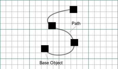
The ![]() Draft PathArray command creates a regular array from a selected object by placing copies along a path. Use the Draft PathLinkArray command to create a more efficient Link array instead. Except for the type of array that is created, Link array or regular array, the Draft PathLinkArray command is identical to this command.
Draft PathArray command creates a regular array from a selected object by placing copies along a path. Use the Draft PathLinkArray command to create a more efficient Link array instead. Except for the type of array that is created, Link array or regular array, the Draft PathLinkArray command is identical to this command.
Both commands can be used on 2D objects created with the Draft Workbench or Sketcher Workbench, but also on many 3D objects such as those created with the Part Workbench, PartDesign Workbench or BIM Workbench.
Draft PathArray
Usage
- Select the object you wish to array.
- Add the path object to the selection. It is also possible to select edges instead. The edges must belong to the same object and they must be connected.
- There are several ways to invoke the command:
- Press the
 Path Array button.
 - Draft: Select the Modification → Array Tools → Path Array option from the menu.
- BIM: Select the Modify → Path Array option from the menu.
- Press the
- The array is created.
- Optionally change the properties of the array in the Property View.
Alignment
The alignment of the elements in a Draft PathArray depends on the properties of the array and the orientation of the source object. The position of the source object is ignored: for the purpose of the array the x, y and z are set to 0. If the DataAlign property of the array is set to false the orientation of the array elements is identical to that of the source object. If it is set to true the X axis of the local coordinate system of each element placement is tangent to the path. The Y and Z axes of the local coordinate systems depend on the DataAlign Mode property of the array. Other array properties involved in the alignment include DataTangent Vector, DataForce Vertical and DataVertical Vector.
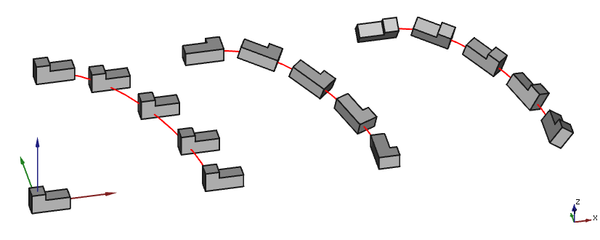
3 arrays based on the same non-planar path. From left to right: Align is false, Align is true with Align Mode Original and Align is true with Align Mode Frenet.
Align Mode
Three modes are available:
Original
This mode comes closest to the single DataAlign Mode available in version 0.18. It relies on a fixed normal vector. If the path is planar this vector is perpendicular to the plane of the path, else a default vector, the positive Z axis, is used. From this normal vector and the local tangent vector (the local X axis) a cross product is calculated. This new vector is used as the local Z axis. The orientation of the local Y axis is determined from the local X and Z axes.
Frenet
This mode uses the local normal vector derived from the path at each element placement. If this vector cannot be determined (for example in the case of a straight segment) a default vector, again the positive Z axis, is used instead. With this vector and the local tangent vector the local coordinate system is determined using the same procedure as in the previous paragraph.
Tangent
This mode is similar to DataAlign Mode Original but includes the possibility to pre-rotate the source object by specifying a DataTangent Vector.
Force Vertical and Vertical Vector
These properties are only available if DataAlign Mode is Original or Tangent. If DataForce Vertical is set to true the local coordinate system is calculated in a different manner. The DataVertical Vector is used as a fixed normal vector. From this normal vector and the local tangent vector (the local X axis) again a cross product is calculated. But now this vector is used as the local Y axis. The orientation of the local Z axis is determined from the local X and Y axes.
Using these properties can be required if one of the edged of the path is (almost) parallel to the default normal of the path.
Notes
- Fused Link arrays are not displayed properly, in the 3D View their elements always appear unfused.
Properties
See also: Property View.
A Draft PathArray object is derived from a Part Feature object and inherits all its properties (with the exception of some View properties that are not inherited by Link arrays). The following properties are additional unless otherwise stated:
Data
Link
The properties in this group are only available for Link arrays. See Std LinkMake for more information.
- DataScale (
Float) - Data (Hidden)Scale Vector (
Vector) - DataScale List (
VectorList) - Data (Hidden)Visibility List (
BoolList) - Data (Hidden)Placement List (
PlacementList) - Data (Hidden)Element List (
LinkList) - Data (Hidden)_ Link Touched (
Bool) - Data (Hidden)_ Child Cache (
LinkList) - Data (Hidden)_ Link Owner (
Integer) - Data (Hidden)Colored Elements (
LinkSubHidden) - DataLink Copy On Change (
Enumeration) - DataLink Transform (
Bool)
Alignment
- DataAlign (
Bool): specifies if the elements in the array are aligned along the path or not. If it isfalseall other properties in this group, except DataExtra Translation, do not apply and are hidden. - DataAlign Mode (
Enumeration): specifies the align mode, which can beOriginal,FrenetorTangent. - DataExtra Translation (
VectorDistance): specifies an additional displacement for each element along the path. - DataForce Vertical (
Bool): specifies whether to override the default normal direction with the value of DataVertical Vector. Only used if DataAlign Mode isOriginalorTangent. - DataReverse Path (
Bool): specifies whether to walk the path backwards. introduced in 1.1 - DataTangent Vector (
Vector): specifies the alignment vector. Only used if DataAlign Mode isTangent. - DataVertical Vector (
Vector): specifies the override for the default normal direction. Only used if DataVertical Vector istrue.
Draft
- DataAlways Sync Placement (
Bool)
Objects
- DataBase (
LinkGlobal): specifies the object to duplicate in the array. - DataExpand Array (
Bool): specifies whether to expand the array in the Tree View to enable the selection of its individual elements. Only available for Link arrays. - DataFuse (
Bool): specifies if overlapping elements in the array are fused or not. introduced in 1.0 - DataPath Object (
LinkGlobal): specifies the object to be used for the path. It must containEdgesin its Part TopoShape. - DataPath Subelements (
LinkSubListGlobal): specifies a list of edges of the DataPath Object. If supplied only these edges are used for the path. - DataPlacement List (
PlacementList): the placement for each element. Appears in the Link group for Link arrays. introduced in 1.1
Spacing
- DataCount (
Integer): specifies the number of elements in the array. - DataEnd Offset (
Length): specifies the length from the end of the path to the last copy. Must be smaller than the length of the path minus the DataStart Offset. introduced in 0.21 - DataSpacing Mode (
Enumeration): specifies how elements are spaced. The options are: introduced in 1.1Fixed count: available path length (minus start and end offsets) is evenly divided to accommodate DataCount elements.Fixed spacing: start at start offset and place new elements after traveling a fixed distance along the path.Fixed count and spacing: same asFixed spacing, but also stop at DataCount elements.
- DataSpacing Pattern (
FloatList): the spacing is multiplied by a corresponding number in this sequence. Only used if DataUse Spacing Pattern istrue, otherwise hidden. introduced in 1.1 - DataSpacing Unit (
Length): the base fixed distance between elements. Only used if DataSpacing Mode isFixed spacingorFixed count and spacing, otherwise hidden. introduced in 1.1 - DataStart Offset (
Length): specifies the length from the start of the path to the first copy. Must be smaller than the length of the path. introduced in 0.21 - DataUse Spacing Pattern (
Bool): use repeating spacing patterns instead of uniform spacing. introduced in 1.1
View
Link
The properties in this group, with the exception of the inherited property, are only available for Link arrays. See Std LinkMake for more information.
- ViewDraw Style (
Enumeration) - ViewLine Width (
FloatConstraint) - ViewOverride Material (
Bool) - ViewPoint Size (
FloatConstraint) - ViewSelectable (
Bool): this is an inherited property that appears in the Selection group for other arrays. - ViewShape Material (
Material)
Base
The properties in this group, with the exception of the inherited property, are only available for Link arrays. See Std LinkMake for more information.
- View (Hidden)Child View Provider (
PersistentObject) - View (Hidden)Material List (
MaterialList) - View (Hidden)Override Color List (
ColorList) - View (Hidden)Override Material List (
BoolList) - View (Hidden)Proxy (
PythonObject): this is an inherited property.
Display Options
The properties in this group are inherited properties. See Part Feature for more information.
- ViewBounding Box (
Bool): this property is not inherited by Link arrays. - ViewDisplay Mode (
Enumeration): for Link arrays it can beLinkorChildView. For other arrays it can be:Flat Lines,Shaded,WireframeorPoints. - ViewShow In Tree (
Bool) - ViewVisibility (
Bool)
Draft
- ViewPattern (
Enumeration): not used. - ViewPattern Size (
Float): not used.
Object style
The properties in this group are not inherited by Link arrays.
Scripting
See also: Autogenerated API documentation and FreeCAD Scripting Basics.
To create a path array use the make_path_array method (introduced in 0.19) of the Draft module. This method replaces the deprecated makePathArray method.
path_array = make_path_array(base_object, path_object,
                             count=4, extra=App.Vector(0, 0, 0), subelements=None,
                             align=False, align_mode="Original", tan_vector=App.Vector(1, 0, 0),
                             force_vertical=False, vertical_vector=App.Vector(0, 0, 1),
                             use_link=True)
base_objectis the object to be arrayed. It can also be theLabel(string) of an object in the current document.path_objectis the path object. It can also be theLabel(string) of an object in the current document.countis the number of elements in the array.extrais a vector that displaces each element.subelementsis a list of edges ofpath_object, for example["Edge1", "Edge2"]. If supplied only these edges are used for the path.- If
alignisTruethe elements are aligned along the path depending on the value ofalign_mode, which can be"Original","Frenet"or"Tangent". tan_vectoris a unit vector that defines the local tangent direction of the elements along the path. It is used whenalign_modeis"Tangent".- If
force_verticalisTruevertical_vectoris used for the local Z direction of the elements along the path. It is used whenalign_modeis"Original"or"Tangent". - If
use_linkisTruethe created elements are App Links instead of regular copies. path_arrayis returned with the created array object.
Example:
import FreeCAD as App
import Draft

doc = App.newDocument()

p1 = App.Vector(500, -1000, 0)
p2 = App.Vector(1500, 1000, 0)
p3 = App.Vector(3000, 500, 0)
p4 = App.Vector(4500, 100, 0)
spline = Draft.make_bspline([p1, p2, p3, p4])
obj = Draft.make_polygon(3, 500)

path_array = Draft.make_path_array(obj, spline, 6)
doc.recompute()

wire = Draft.make_wire([p1, -p2, -p3, -p4])
path_array2 = Draft.make_path_array(obj, wire, count=3, extra=App.Vector(0, -500, 0), subelements=["Edge2", "Edge3"], align=True, force_vertical=True)
doc.recompute()
This page is retrieved from https://wiki.freecad.org/Draft_PathArray