| Topic |
|---|
| Modeling |
| Level |
| Beginner |
| Time to complete |
| 1 hour |
| Authors |
| EmmanuelG |
| FreeCAD version |
| 0.16 or greater |
| Example files |
| Thingiverse 2403310 |
| See also |
| None |
A daily-life problem
Periuțele electrice de dinți mai rar vin cu un suport pentru cap, în timp ce într-o familie, veți vedea adesea mai multe capete folosite cu un singur corp. Mulți oameni se confruntă cu o problemă comună, ceea ce duce la o varietate de soluții, după cum puteți vedea pe Thingiverse (200 la 800 de proiecte sunt legate de acest lucru). Iată primul răspuns și cum să îl proiectăm.
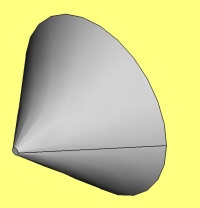
This tutorial will take you through the steps needed to model the part shown in the image below using basic tools from the Part Design Workbench (many of the tools and capabilities are not covered).
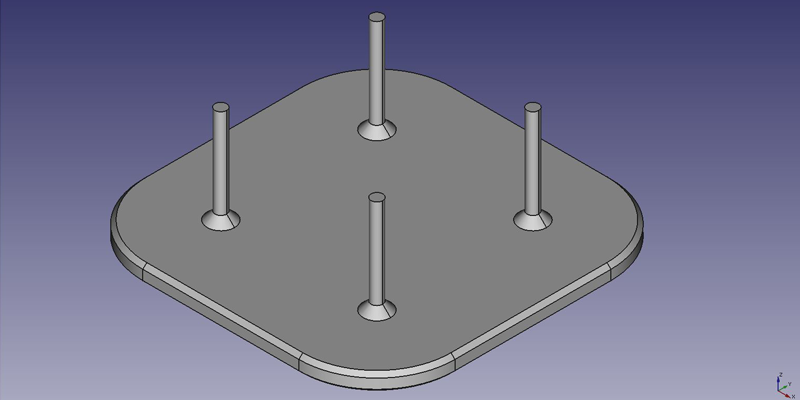
First idea : a plate
First idea : a plate
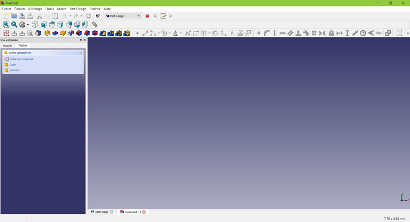
- From the start-page, select
 Part Design, or create a new document and select the Part Design workbench.
Create a sketch
- Click on
 New sketch. Either from the contextual task menu at the left, or the toolbar above or from the Part Design menu at the top.
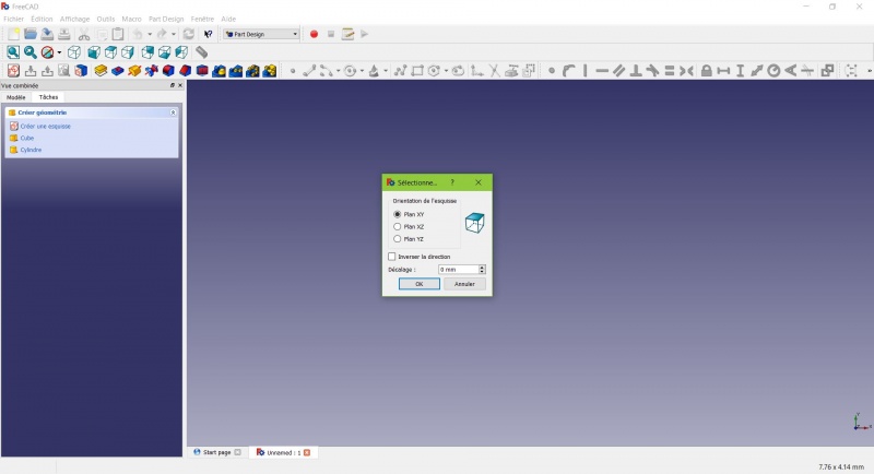
A dialog prompts you to choose the sketch orientation and provide an offset.
- We will pick the XY Plane as shown in the image above (that orientation correspond to the common build plate of most 3D printers), then click OK.
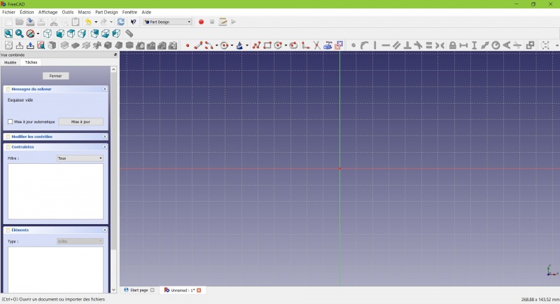
You now are facing the XY plane from above, and have access to the drawing tools.
- Click on
 Rectangle.
 - Click to place a first point.
- Click to place the opposite corner.
- Press ESC or click the right mouse button to stop using the tool.
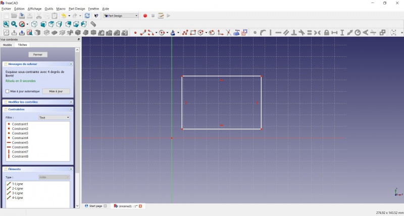
You now have a floating rectangle of unspecified dimensions.
- Click on a line of the rectangle, you now have access to the constraint tools at the right of the toolbar (depending of the size of your screen you may need to drag them to the left in order to see them all)
- Click on
 Distance
 - A dialog prompts you to set a dimension. Enter 80mm, click OK.
- Repeat with the other side of the rectangle, also 80mm.
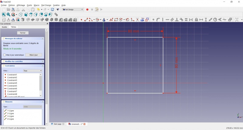
You now have a floating square.
- Click on the lower left point of the square.
- Click on the origin of the XY plane (at the intersection of the two thick lines).
- Click on
 Coincident.
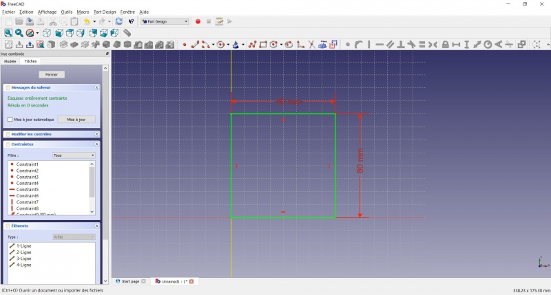
You now have a totally constrained sketch, as you are told by the solver on the left and the change of color. It is a good practice to always have a totally constrained sketch.
An under-constrained sketch can leave room for unwanted change, if you modify something later on.
On the opposite, an over-constrained sketch is also not good. In that case the solver warn you of redundant constraints and you should remove some of them.
- To leave the sketch, click either on the "Close" button on the left, or the
 icon in the toolbar, or press ESC.
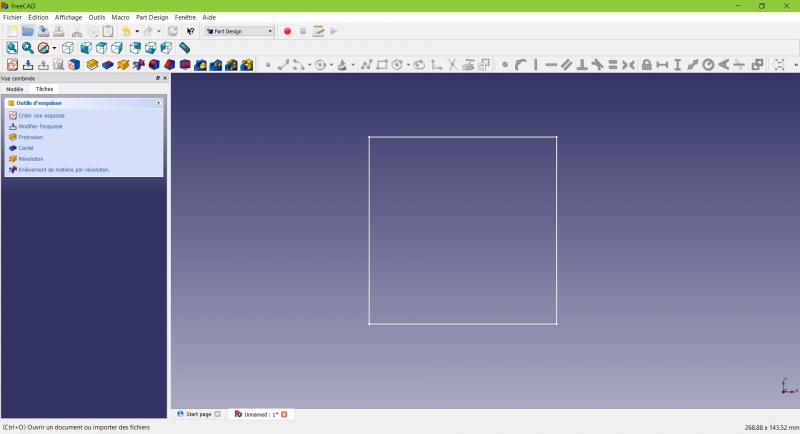
You now only see the square, and the contextual task menu on the left show you more options than before.
Create a pad
- Click on
 Axonometric among the standard views, to better see what will happen.
 - Click on
 Pad.
Pad. - Enter 4mm and click OK.
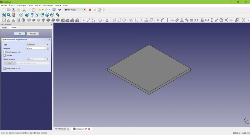
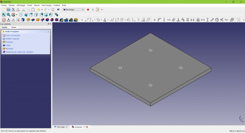
Your sketch is now in volume!
Create a sketch on it
- Select the upper face
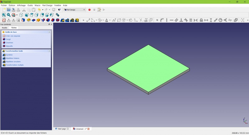
The color of the face change and you have more options in the contextual task menu.
- Click on New sketch. As a face was selected it will not ask you to choose a plane.
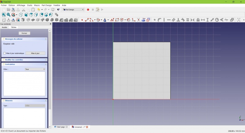
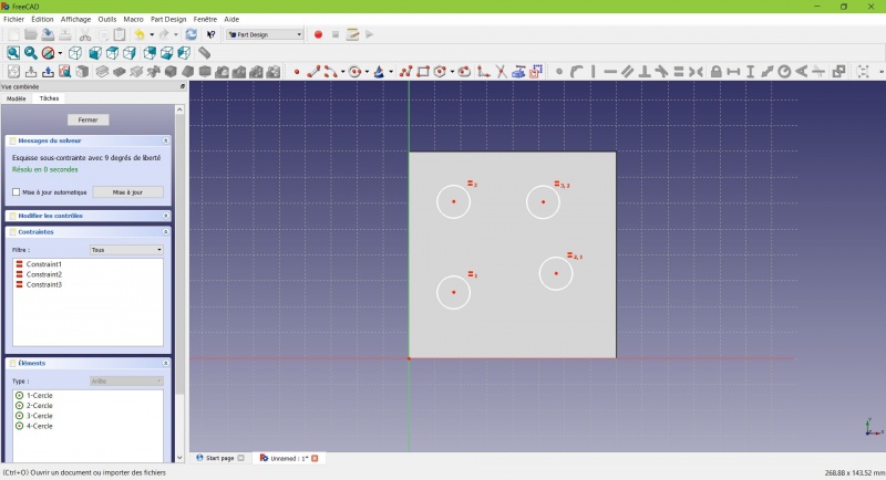
- Click on
 Circle, click to place the center, move the pointer and click to define the radius.
 - Draw 4 circles on the pad (of any size)
- Press ESC or click the right mouse button to stop using the tool.
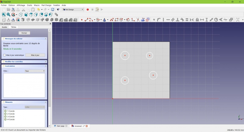
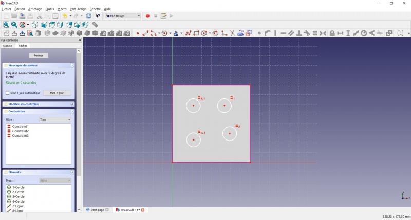
- Select the circles
- Click on
 Equal Length
Now the circles share the same radius.
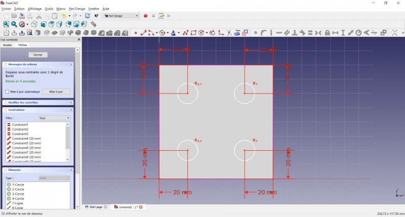
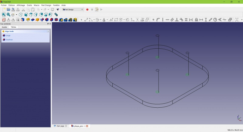
- Click on
 External geometry.
 - Click on the four sides of the square, it add lines, color magenta.
Theses lines will serve as reference to position the circles.
- Click on Distance.
- Click on a center of a circle.
- Click on a magenta line.
- Set distance (20mm from each side).
- Click on a circle
- Click on
 Radius and set it at 1,5mm.
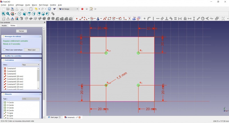
- To leave the sketch, click either on the "Close" button on the left, or the icon in the toolbar, or press ESC.
Create a pad
- Click on Axonometric among the standard views, to better see what will happen.
- Click on Pad.
- Enter 25mm and click OK.
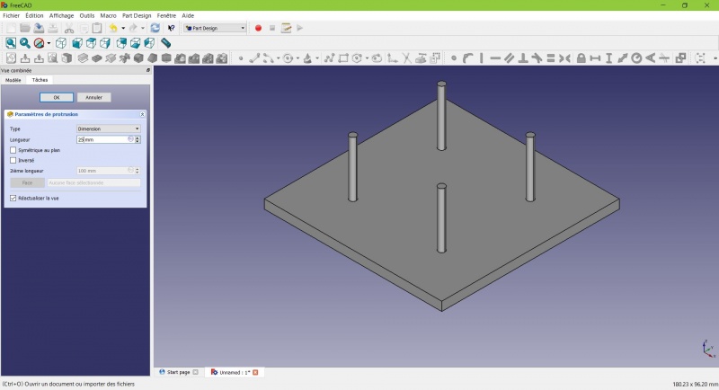
You have the basic shape, it just need final touches.
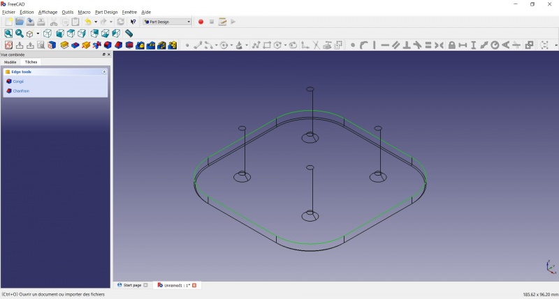
Rounding the corners
- Holding CTRL click on the vertical edge at each corner to select the four of them.
Don't hesitate to help you by switching the display mode (just at the left of the Axonometric View) between ![]() Wireframe and
Wireframe and ![]() Wireframe and shadow.
Wireframe and shadow.
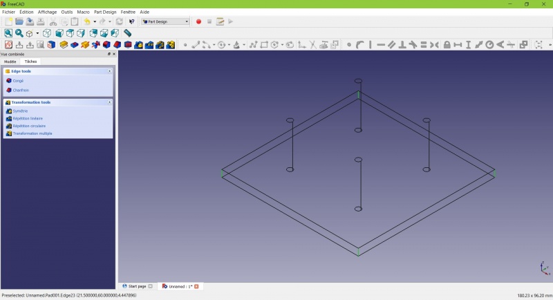
- Click on
 Fillet.
 - Set the radius at 20mm.
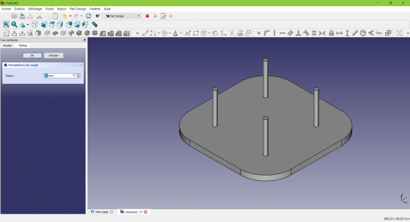
Much better.
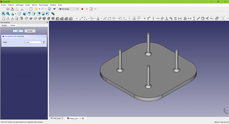
Making it more robust
We need to add material at the base of the cylinders to make them less prone to snap. Because of the printing orientation these small surfaces will be fragile at the junction with the base.
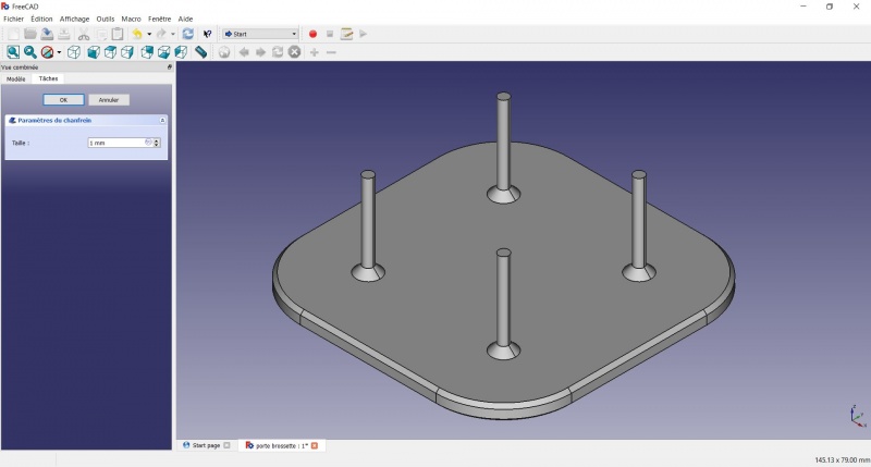
- Select the circles at the base of the cylinders
- Click on
 Chamfer.
 - Set it to 2mm.
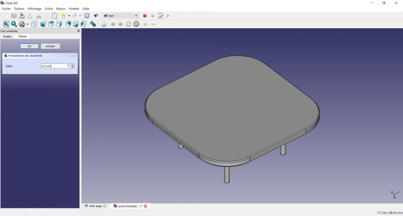
Chamfer the edges
- Select the face under the base, add a Chamfer of 0,5mm.
The first layer of plastic is often being squashed a little too much, this will compensate that and save you time in cleaning the model. If the first layer is ok that will make it only nicer
- Select the edges at the border of the upper face (holding CTRL ).
- Add a Chamfer of 1mm. This one is only aesthetic.
Tadaa!
Export as a .STL
- In the Combo View on the left, select the tree view instead of the contextual task menu, click on the last feature (the chamfer).
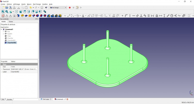
- Now you can select "Export..." from the File menu at the top left, and select the file format .STL.
- Just print it :-)
Inspiration
The above model make a good starting point to use FreeCAD, but as a toothbrush head stand it have its flaws : due to the print orientation and small surface the sticks are prone to break.
Inspired by the variety of solutions other people came up with, we will make this second version which will be much better.
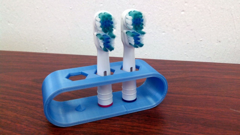
Don't worry it is often needed to go through several revision for an idea (e.g. : once the prototype on the picture was used, we added more space between the heads so that they should not touch).
In this second part you will also learn to use more tools, like the powerful Linear repetition.
Second idea : a band
- Create a new document and select the
 Part Design workbench.
Create a sketch
- Create a New sketch, on the XY plane.
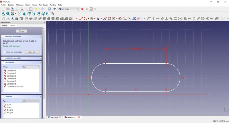
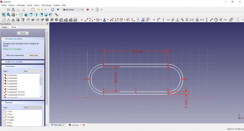
- Draw a
 Slot
Slot
- Click to place the first center
- Move to define the length and radius
- Click to set the second center.
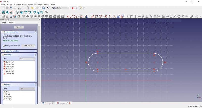
You now have a floating slot of unspecified dimensions.
- Click on one of the horizontal lines of the slot
- Click on Distance
- A dialog prompts you to set a dimension. Enter 75mm, click OK.
- that's for a 3 head stand, count 25mm for each, if you want more
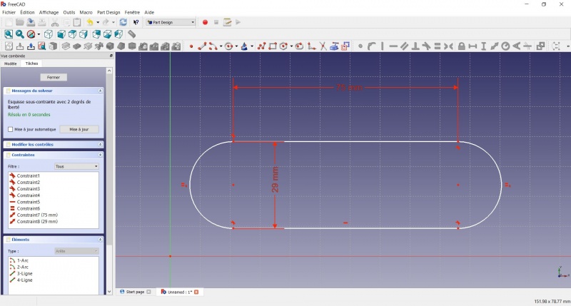
- Click on one point of the horizontal line
- Click on one point of the other horizontal line
- Click on Distance
- A dialog prompts you to set a dimension. Enter 29mm, click OK.
- Draw a Slot around the first slot.
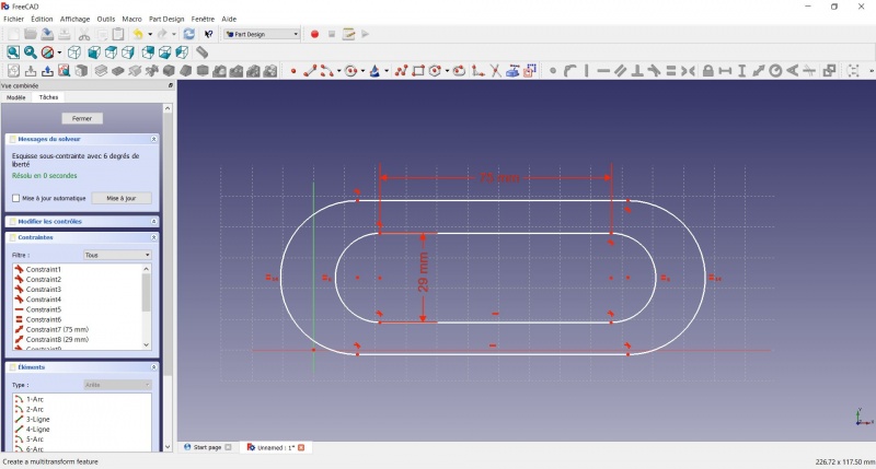
- Make the centers of the second slot coincident with the centers of the first slot with Coincident.
- Click on one point of the horizontal line of the first slot
- Click on one point of the nearest horizontal line of the second slot
- Click on Distance
- A dialog prompts you to set a dimension. Enter 3mm, click OK.
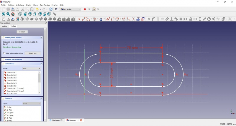
- To make the sketch fully constrained
- Click on the lower left point of the second slot
- Click on the origin of the XY plan
- Click on Coincident
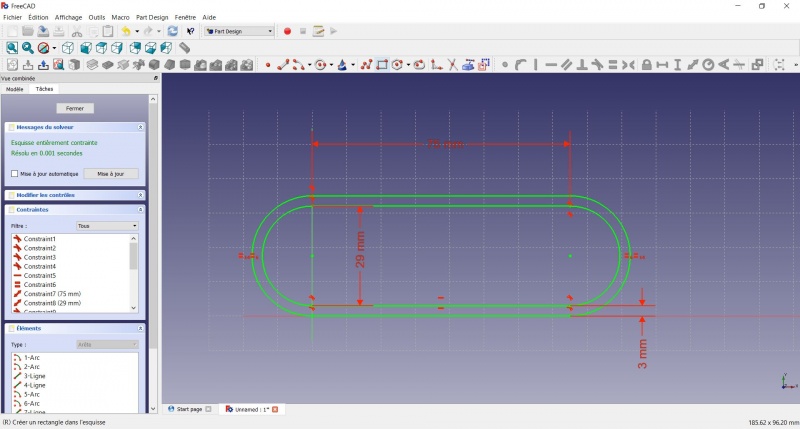
- To leave the sketch, click either on the "Close" button on the left, or the icon in the toolbar, or press ESC.
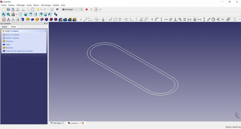
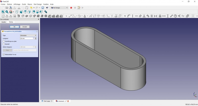
Create a pad
- Click on Axonometric among the standard views, to better see what will happen.
- Click on Pad.
- Enter 30mm and click OK.
Create a sketch on it
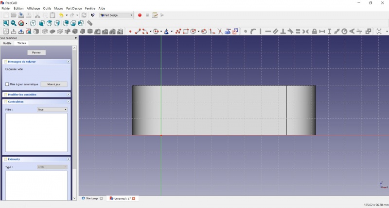
- Select the upper face
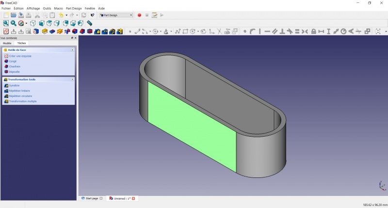
- Create a New sketch. As a face was selected it will not ask you to choose a plane.
- Draw an
 Hexagon
- Click to place the center
- Move to define the radius
- Click to set
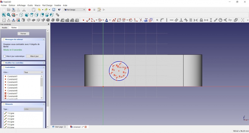
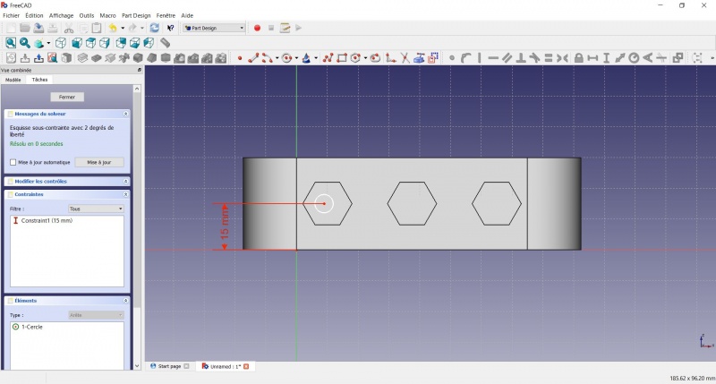
- Click on an edge of the hexagon
- Click on
 Horizontal
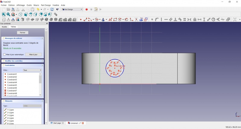
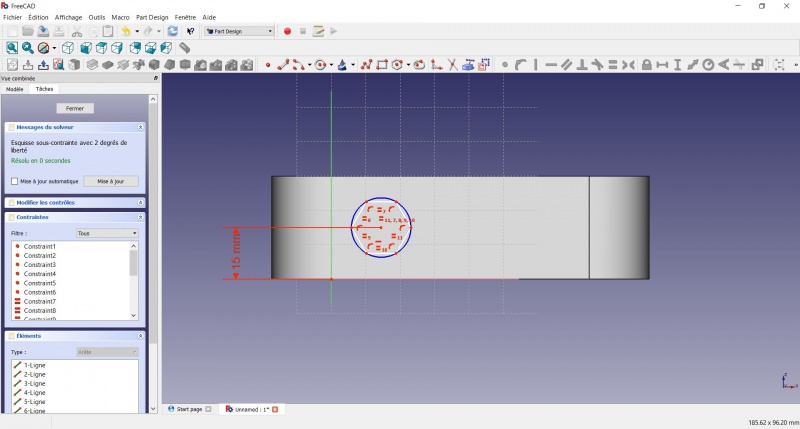
- Click on the center of the hexagon
- Click on the horizontal line of the XY plane
- Click on Distance
- A dialog prompts you to set a dimension. Enter 15mm, click OK.
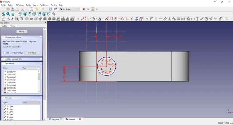
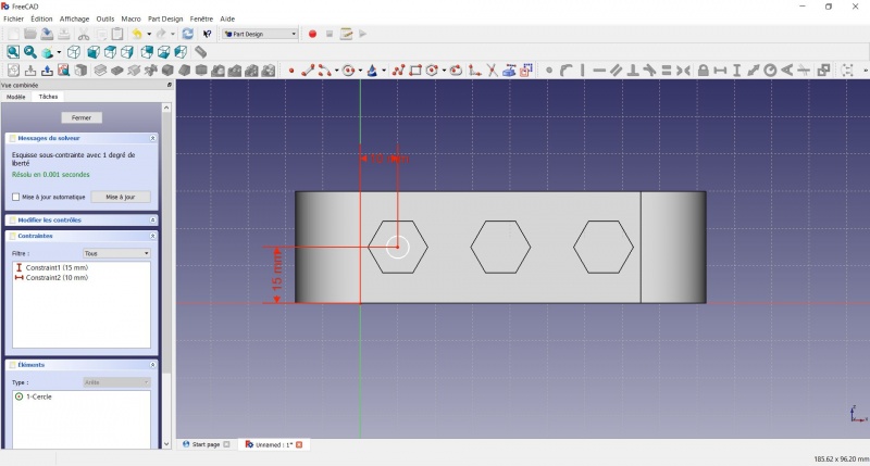
- Click on the center of the hexagon
- Click on the vertical of the XY plane
- Click on Distance
- A dialog prompts you to set a dimension. Enter 10mm, click OK.
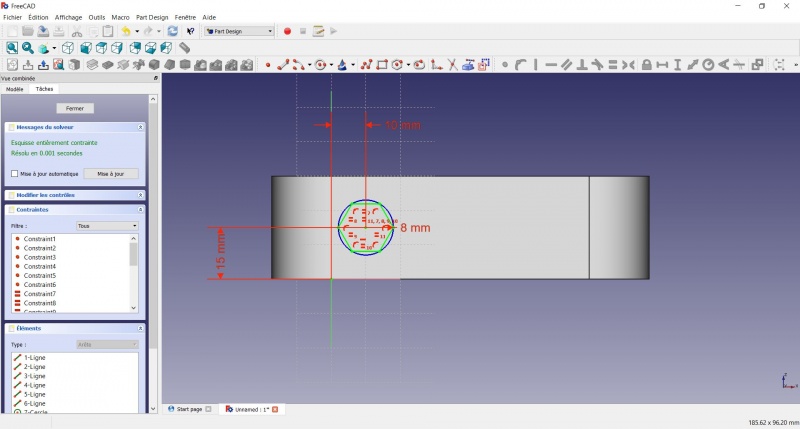
- Click on the blue circle of the hexagon
- Click on Radius
- A dialog prompts you to set a dimension. Enter 8mm, click OK.
- To leave the sketch, click either on the "Close" button on the left, or the icon in the toolbar, or press ESC.
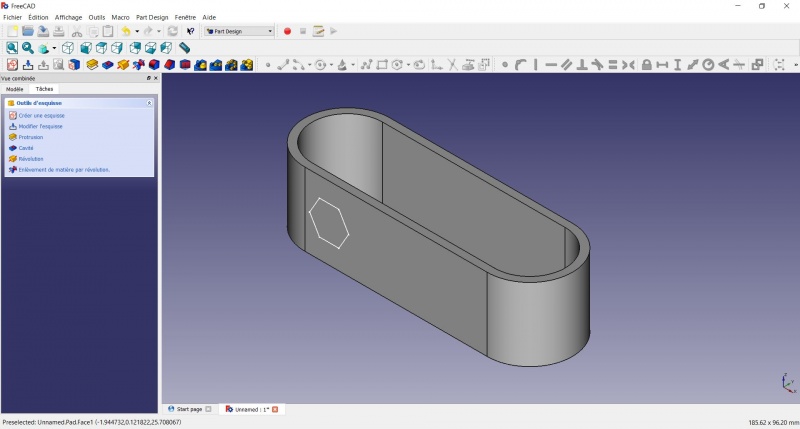
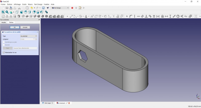
Create a hole
- Click on Axonometric among the standard views, to better see what will happen.
- Click on
 Pocket.
 - Select to the first in the dropdown menu and click OK.
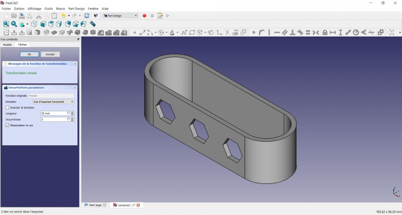
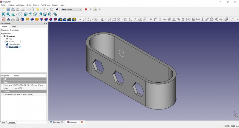
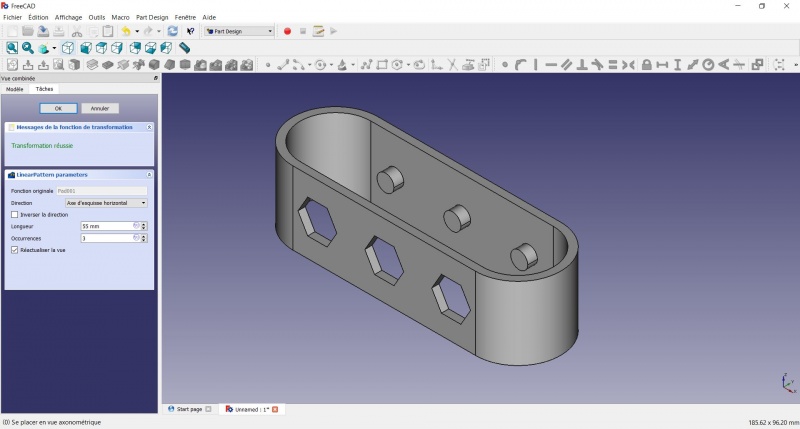
Linear repetition
- In the Combo View on the left, select the tree view instead of the contextual task menu, click on the pocket feature.
- Click on
 LinearPattern.
 - Set the length at 55mm and occurencies at 3, then click OK.
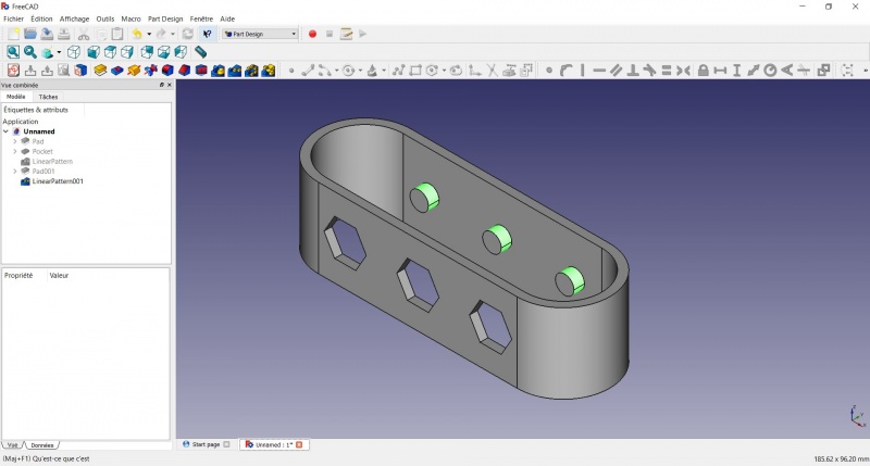
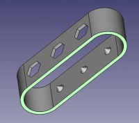
Create a sketch on it
- Select the inner face
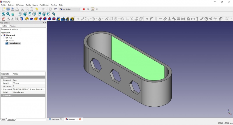
- Create a New sketch. As a face was selected it will not ask you to choose a plane.

- Click on Circle, click to place the center, move the pointer and click to define the radius.
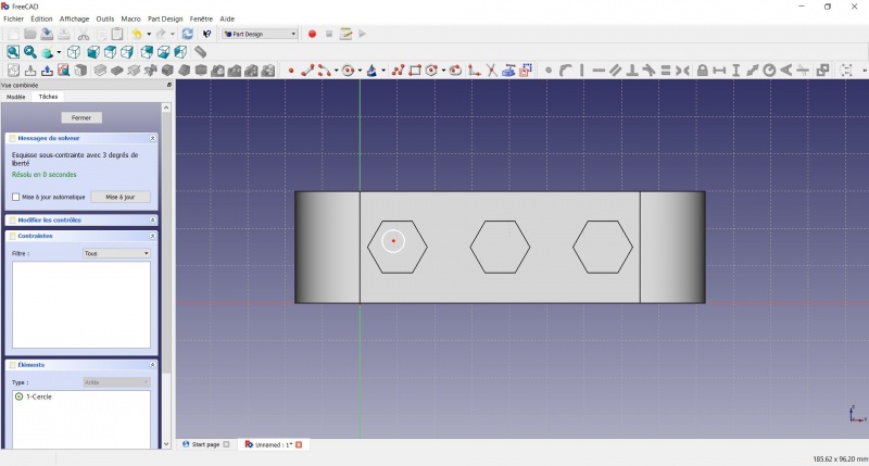
- Click on the center of the circle
- Click on the horizontal line of the XY plane
- Click on Distance
- A dialog prompts you to set a dimension. Enter 15mm, click OK.
- Click on the center of the circle
- Click on the vertical of the XY plane
- Click on Distance
- A dialog prompts you to set a dimension. Enter 10mm, click OK.
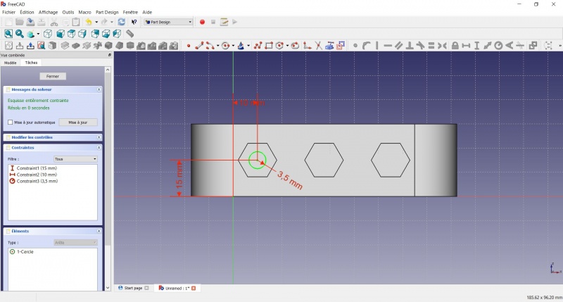
- Click on the circle
- Click on Radius
- A dialog prompts you to set a dimension. Enter 3.5mm, click OK.
- To leave the sketch, click either on the "Close" button on the left, or the icon in the toolbar, or press ESC.
Create a pad
- Click on Axonometric among the standard views, to better see what will happen.
- Click on Pad.
- Enter 4mm and click OK.

Linear repetition
- In the Combo View on the left, select the tree view instead of the contextual task menu, click on the pad feature.
- Click on LinearPattern.
- Set the length at 55mm and occurencies at 3, then click OK.
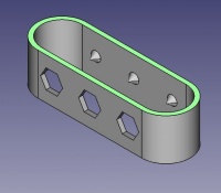
Draft
- Select the side of each round pads
- Click on
 Draft.
 - Set the draft angle at 40°.
- Click on "Neutral plane" and select the face on which the sketch is drawn.
- Tick "Invert the draft direction".
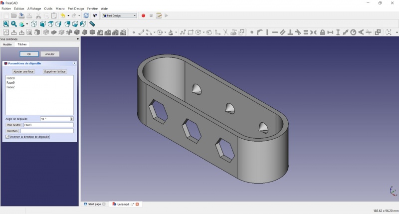
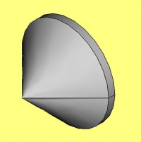
We could have used a chamfer to do something similar, but the draft is more appropriate in this case.
Chamfer = left / Draft = right
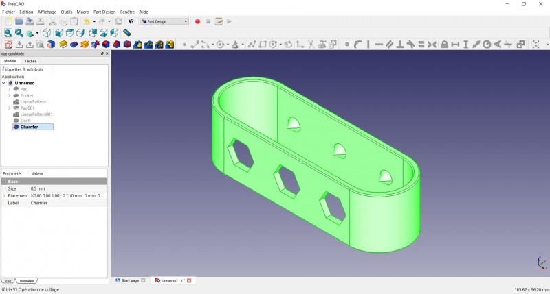
Finishes
- Holding CTRL select the bottom and top faces.
- Add a Chamfer of 0,5mm.
- Add a
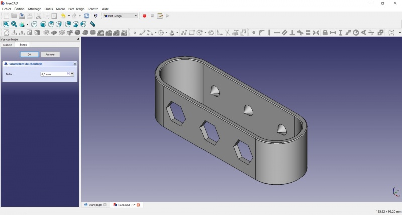
Perfect!
Export as a .STL
- In the Combo View on the left, select the tree view instead of the contextual task menu, click on the last feature (the chamfer).
- Now you can select "Export..." from the File menu at the top left, and select the file format .STL.
- Print it instead of the first version or to replace it if it eventually broke ;-)
Această pagină este preluată de la https://wiki.freecad.org/Toothbrush_Head_Stand