| Argomento |
|---|
| Modellazione |
| Livello di difficoltà |
| Principiante |
| Tempo di esecuzione |
| 1 hour |
| Autori |
| EmmanuelG |
| Versione di FreeCAD |
| 0.16 o successive |
| Files di esempio |
| Thingiverse 2403310 |
| Vedere anche |
| Nessuno |
Un problema della vita quotidiana
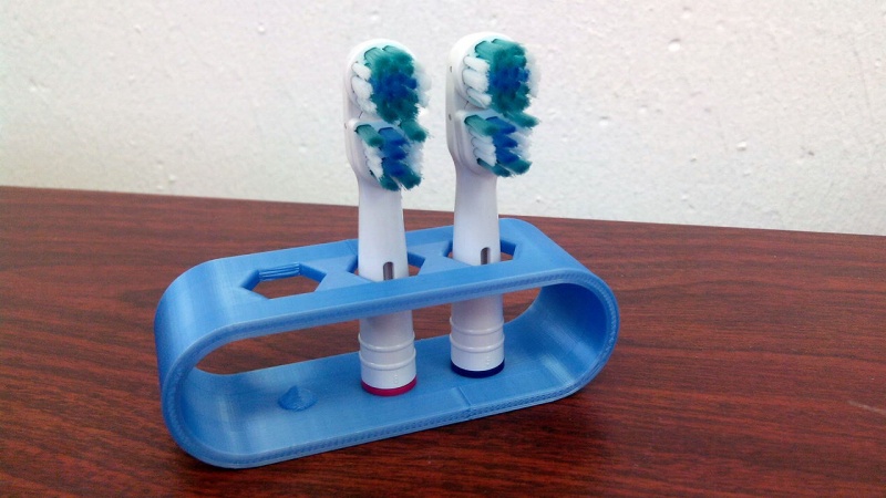
Gli spazzolini elettrici raramente sono dotati di supporto per la testina, mentre in famiglia è frequente trovare più testine utilizzate con un unico corpo. Molte persone che si trovano ad affrontare un problema comune hanno portato a una varietà di soluzioni, come si può vedere su Thingiverse (200-800 progetti sono correlati a questo argomento). Ecco il primo esempio e come progettarlo.
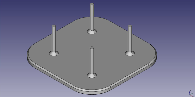
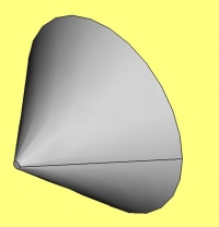
Questo tutorial ti guiderà attraverso i passaggi necessari per modellare il componente mostrato nell'immagine sottostante utilizzando gli strumenti di base di Part Design Workbench (molti degli strumenti e delle funzionalità non sono trattati).
Prima idea: un piatto
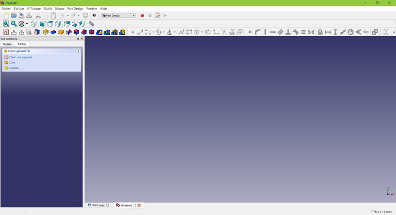
Dalla pagina iniziale, seleziona "Part Design" oppure crea un nuovo documento e seleziona l'ambiente di lavoro "Part Design".
Creare uno schizzo
Fai click su "nuovo schizzo" dal menu contestuale delle attività a sinistra, dalla barra degli strumenti in alto o dal menu Part Design in alto.
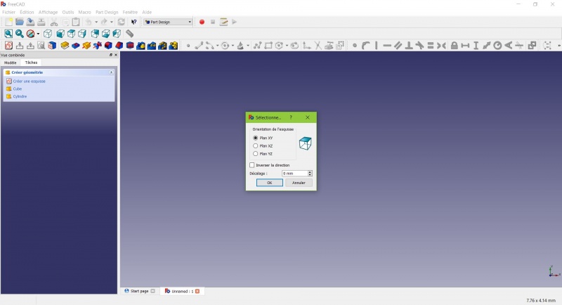
Viene visualizzata una finestra di dialogo che richiede di scegliere l'orientamento dello schizzo e di specificare un offset.
Selezioneremo il piano XY come mostrato nell'immagine sopra (tale orientamento corrisponde al piano di stampa comune alla maggior parte delle stampanti 3D), quindi faremo clic su OK.
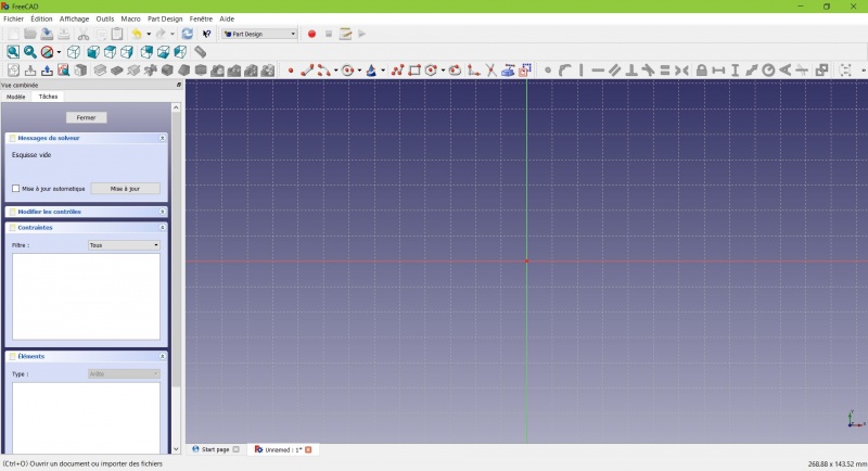
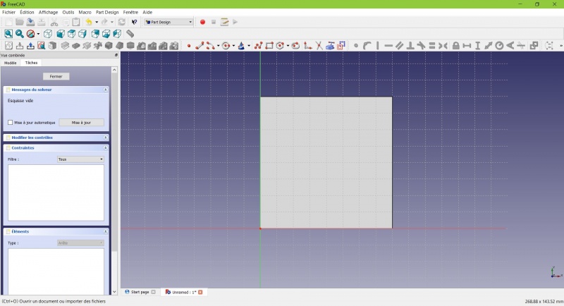
Ora ti trovi di fronte al piano XY visto dall'alto e hai accesso agli strumenti di disegno.
- Fai clic su
 Rettangolo.
- Fai clic per posizionare il primo punto.
- Fai clic per posizionare l'angolo opposto.
- Premi ESC o fai clic con il pulsante destro del mouse per interrompere l'utilizzo dello strumento e accedere agli strumenti di disegno.
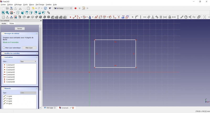
Ora hai un rettangolo mobile con dimensioni non specificate.
- Fai clic su una linea del rettangolo: ora hai accesso agli strumenti di vincolo a destra della barra degli strumenti (a seconda delle dimensioni dello schermo, potrebbe essere necessario trascinarli verso sinistra per visualizzarli tutti).
- Fai clic su
 Distanza
 - Si aprirà una finestra di dialogo che ti chiederà di impostare una dimensione. Inserisci 80 mm e fai clic su OK.
- Ripeti l'operazione con l'altro lato del rettangolo, sempre impostando 80 mm.
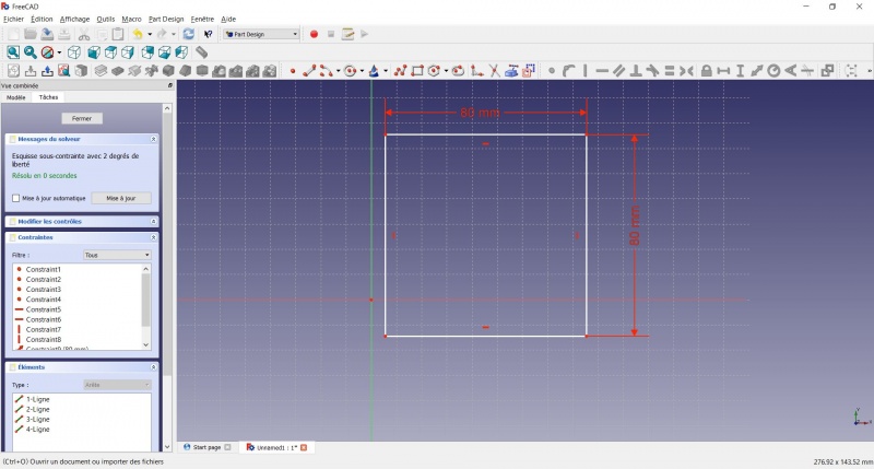
Ora hai un quadrato mobile.
- Clicca sul punto in basso a sinistra del quadrato.
- Clicca sull'origine del piano XY (all'intersezione delle due linee spesse).
- Clicca su
 Coincident.
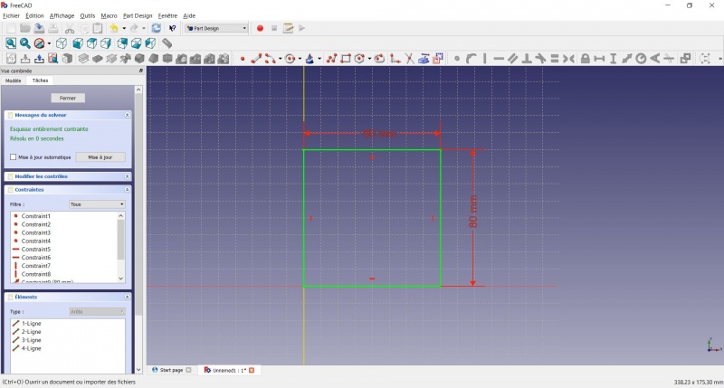
Ora hai uno schizzo completamente vincolato, come indicato dal risolutore a sinistra e dal cambio di colore. È buona norma avere sempre uno schizzo completamente vincolato.
Uno schizzo con vincoli insufficienti può lasciare spazio a modifiche indesiderate, se si modifica qualcosa in seguito. Ora abbiamo uno schizzo con vincoli totali, come indicato dal risolutore a sinistra e dal cambio di colore. È buona norma avere sempre uno schizzo con vincoli totali.
Al contrario, anche uno schizzo eccessivamente vincolato non è una buona cosa. In tal caso, il risolutore ti avvisa della presenza di vincoli ridondanti e dovresti rimuoverne alcuni.
- Per uscire dallo schizzo, fai clic sul pulsante "Chiudi" a sinistra, oppure sull'icona
 nella barra degli strumenti, oppure premi ESC. Al contrario, uno schizzo eccessivamente vincolato non è una buona cosa. In tal caso, il risolutore ti avvisa della presenza di vincoli ridondanti e dovresti rimuoverne alcuni.
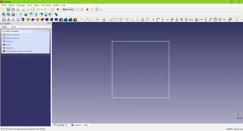
Ora vedi solo il quadrato e il menu contestuale delle attività a sinistra ti mostra più opzioni rispetto a prima.
Creare un solido estruso
- Fai clic su
 Assonometrica tra le viste standard per visualizzare meglio il risultato.
- Fai clic su
 Estrusione.
- Inserisci 4 mm e fai clic su OK.
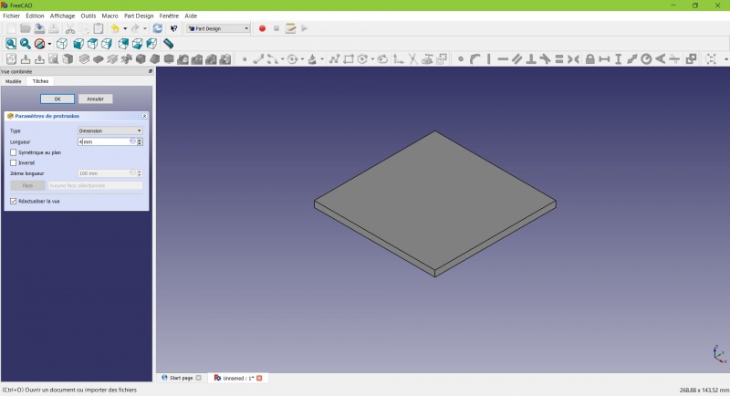
Il tuo schizzo è ora un solido!
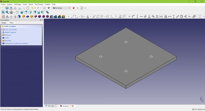
Realizza uno schizzo su di esso
Seleziona la faccia superiore
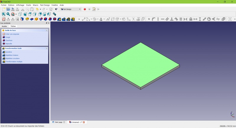
Il colore della faccia cambia e tu hai altre opzioni nel menu contestuale delle azioni.
- Fai clic su
 Nuovo schizzo. Poiché è stata selezionata una faccia, non ti verrà chiesto di scegliere un piano.
- Fai clic su
 Cerchio, fai clic per posizionare il centro, sposta il puntatore e fai clic per definire il raggio.
- Disegna 4 cerchi sul pad (di qualsiasi dimensione).
- Premi ESC o fai clic con il pulsante destro del mouse per interrompere l'utilizzo dello strumento.
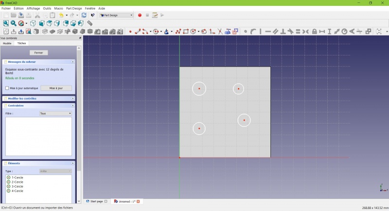
- Seleziona i cerchi
- Fai clic su
 Lunghezza uguale
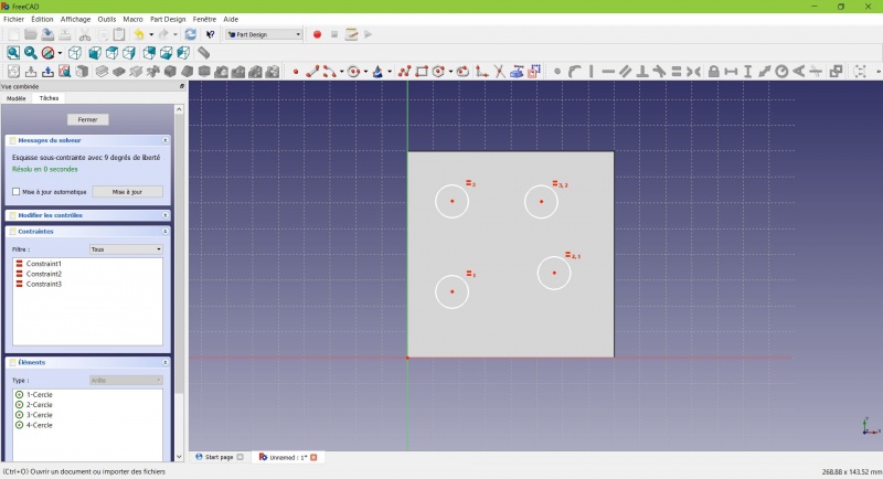
Ora i cerchi hanno lo stesso raggio.
- Fai clic su
 Geometria esterna.
- Fai clic sui quattro lati del quadrato, verranno aggiunte delle linee di colore magenta.
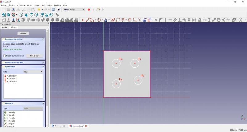
Queste linee serviranno da riferimento per posizionare i cerchi. ![]() Geometria esterna.
Geometria esterna.
- Clicca sui quattro lati del quadrato per aggiungere delle linee di colore magenta.
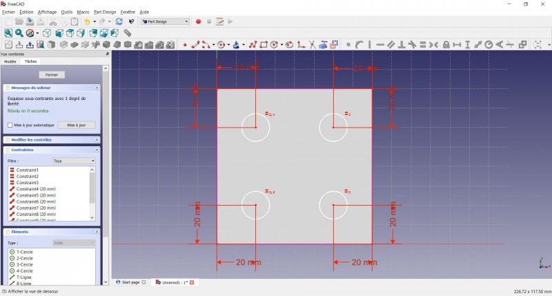
- Fai clic su Distanza.
- Fai clic sul centro di un cerchio.
- Fai clic su una linea magenta.
- Imposta la distanza (20 mm da ciascun lato).
- Fai clic su un cerchio
- Fai clic su
 Raggio e impostalo a 1,5 mm.
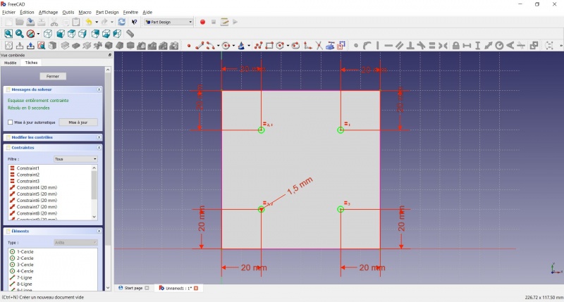
- Per uscire dallo schizzo, fai clic sul pulsante "Chiudi" a sinistra, oppure sull'icona nella barra degli strumenti, oppure premi ESC.
Creare un solido estruso
- Fai clic su Assonometrica tra le viste standard per visualizzare meglio il risultato.
- Fai clic su Pad.
- Inserisci 25 mm e fai clic su OK.
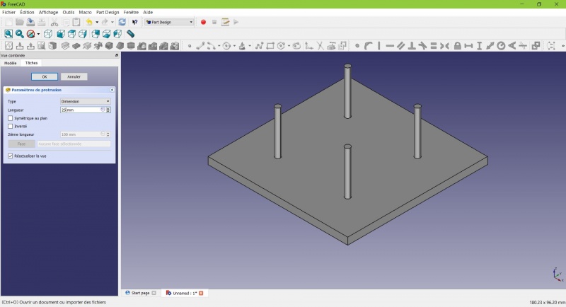
La forma di base c'è, mancano solo i ritocchi finali.
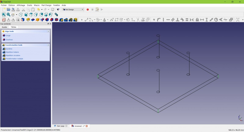
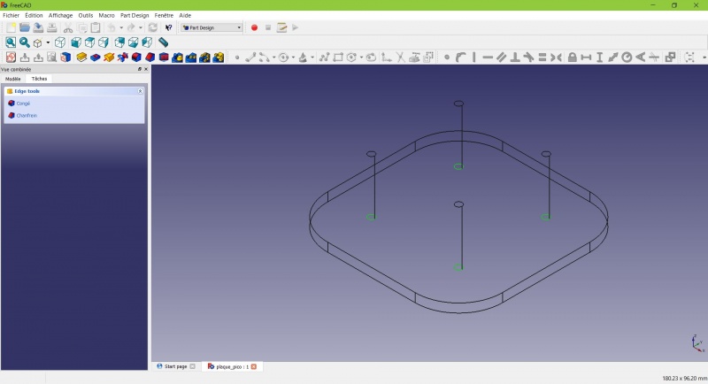
Arrotondiamo gli spigoli
- Tenendo premuto CTRL, fai clic sul bordo verticale in ciascun angolo per selezionarli tutti e quattro.
Non esitare ad aiutarti cambiando la modalità di visualizzazione (appena a sinistra della Vista assonometrica) tra ![]() Wireframe e
Wireframe e ![]() Wireframe e ombra.ng CTRL fai clic sul bordo verticale in ogni angolo per selezionarli tutti e quattro.
Wireframe e ombra.ng CTRL fai clic sul bordo verticale in ogni angolo per selezionarli tutti e quattro.
- Fare clic su
 Raccordo.
- Impostare il raggio a 20 mm.
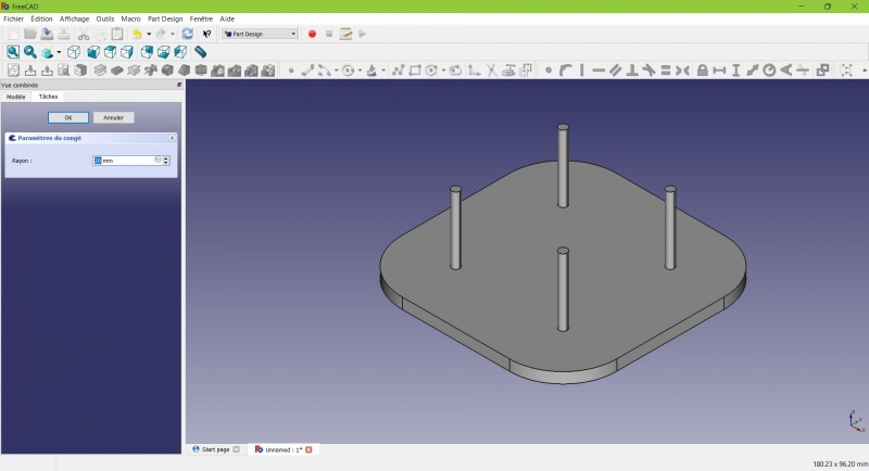
Much better.
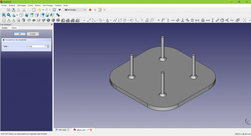
Making it more robust
We need to add material at the base of the cylinders to make them less prone to snap. Because of the printing orientation these small surfaces will be fragile at the junction with the base.
- Select the circles at the base of the cylinders
- Click on
 Chamfer.
 - Set it to 2mm.
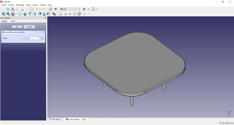
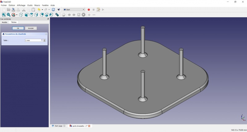
Chamfer the edges
- Select the face under the base, add a Chamfer of 0,5mm.
The first layer of plastic is often being squashed a little too much, this will compensate that and save you time in cleaning the model. If the first layer is ok that will make it only nicer
- Select the edges at the border of the upper face (holding CTRL ).
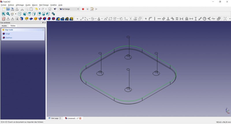
- Add a Chamfer of 1mm. This one is only aesthetic.
Tadaa!
Export as a .STL
- In the Combo View on the left, select the tree view instead of the contextual task menu, click on the last feature (the chamfer).
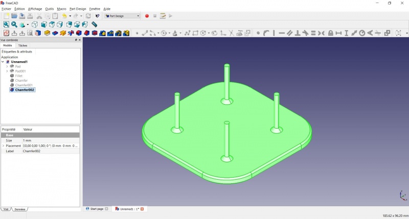
- Now you can select "Export..." from the File menu at the top left, and select the file format .STL.
- Just print it :-)
Inspiration
The above model make a good starting point to use FreeCAD, but as a toothbrush head stand it have its flaws : due to the print orientation and small surface the sticks are prone to break.
Inspired by the variety of solutions other people came up with, we will make this second version which will be much better.
Don't worry it is often needed to go through several revision for an idea (e.g. : once the prototype on the picture was used, we added more space between the heads so that they should not touch).
In this second part you will also learn to use more tools, like the powerful Linear repetition.
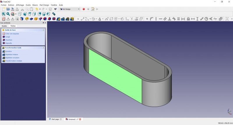
Second idea : a band
- Create a new document and select the
 Part Design workbench.
Create a sketch
- Create a New sketch, on the XY plane.
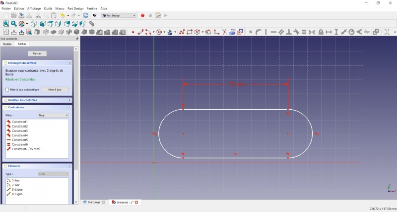
- Draw a
 Slot
Slot
- Click to place the first center
- Move to define the length and radius
- Click to set the second center.
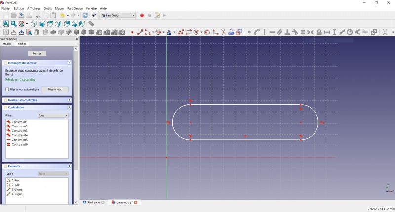
You now have a floating slot of unspecified dimensions.
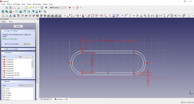
- Click on one of the horizontal lines of the slot
- Click on Distance
- A dialog prompts you to set a dimension. Enter 75mm, click OK.
- that's for a 3 head stand, count 25mm for each, if you want more
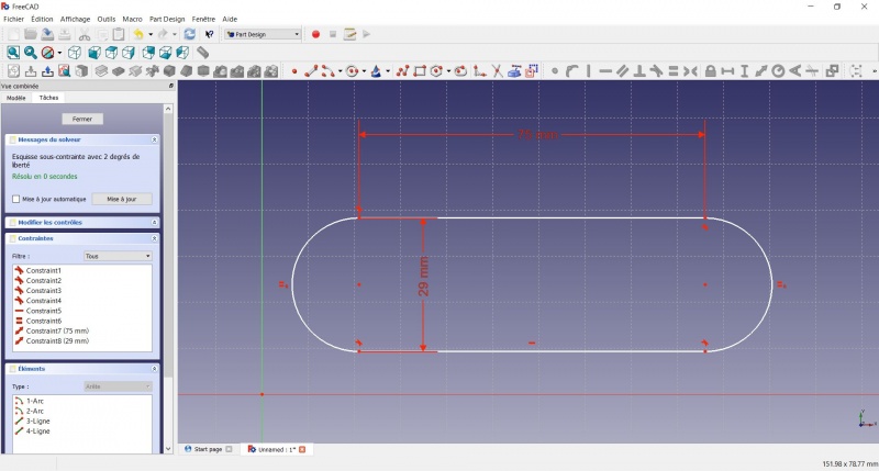
- Click on one point of the horizontal line
- Click on one point of the other horizontal line
- Click on Distance
- A dialog prompts you to set a dimension. Enter 29mm, click OK.
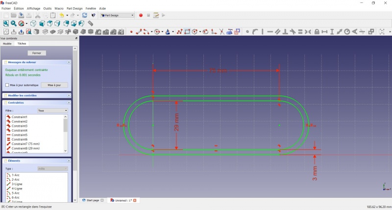
- Draw a Slot around the first slot.
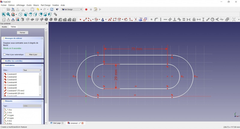
- Make the centers of the second slot coincident with the centers of the first slot with Coincident.
- Click on one point of the horizontal line of the first slot
- Click on one point of the nearest horizontal line of the second slot
- Click on Distance
- A dialog prompts you to set a dimension. Enter 3mm, click OK.
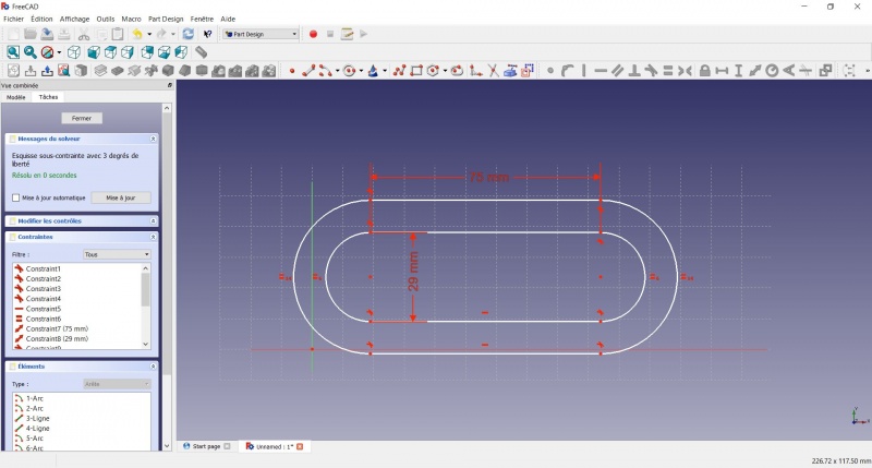
- To make the sketch fully constrained
- Click on the lower left point of the second slot
- Click on the origin of the XY plan
- Click on Coincident
- To leave the sketch, click either on the "Close" button on the left, or the icon in the toolbar, or press ESC.
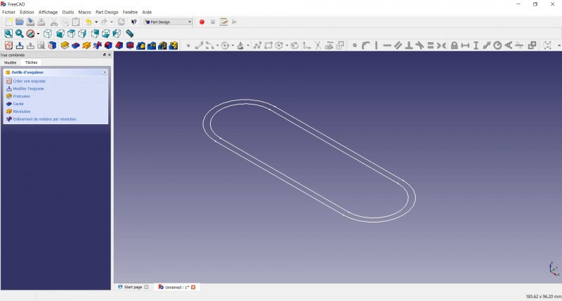
Create a pad
- Click on Axonometric among the standard views, to better see what will happen.
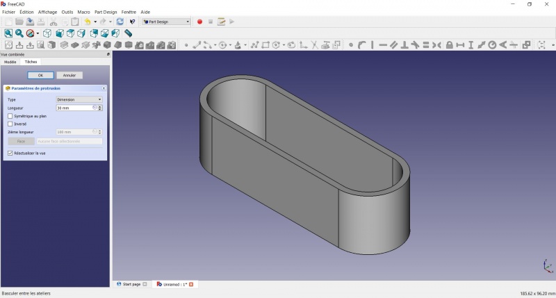
- Click on Pad.
- Enter 30mm and click OK.
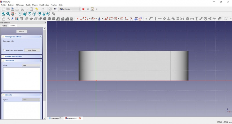
Create a sketch on it
- Select the upper face
- Create a New sketch. As a face was selected it will not ask you to choose a plane.
- Draw an
 Hexagon
- Click to place the center
- Move to define the radius
- Click to set
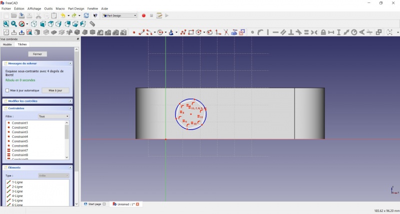
- Click on an edge of the hexagon
- Click on
 Horizontal
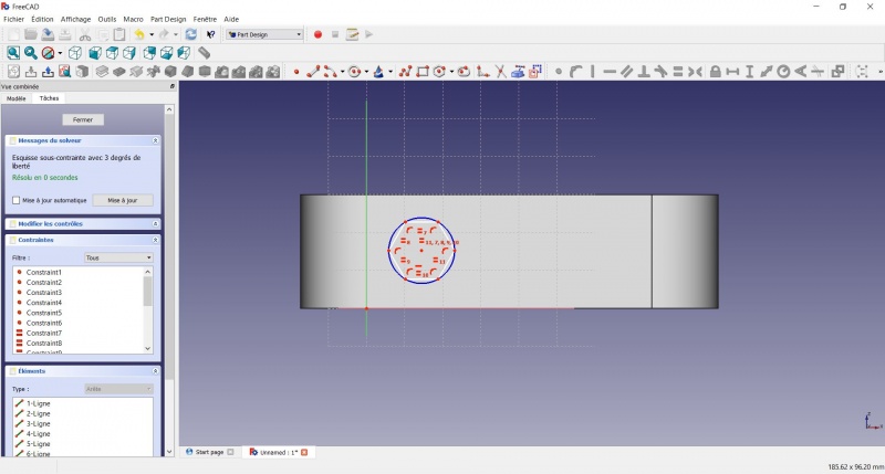
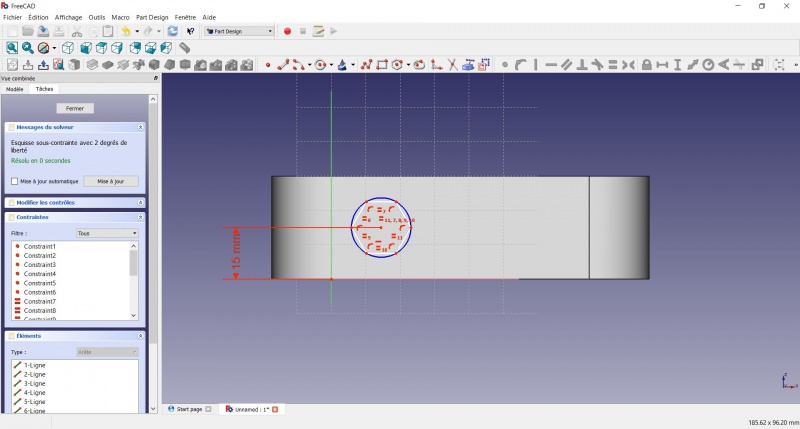
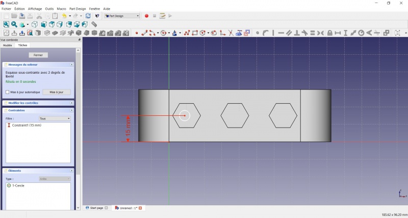
- Click on the center of the hexagon
- Click on the horizontal line of the XY plane
- Click on Distance
- A dialog prompts you to set a dimension. Enter 15mm, click OK.
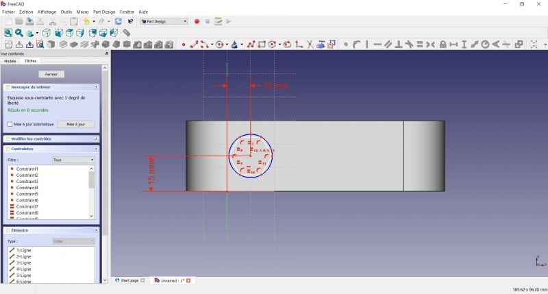
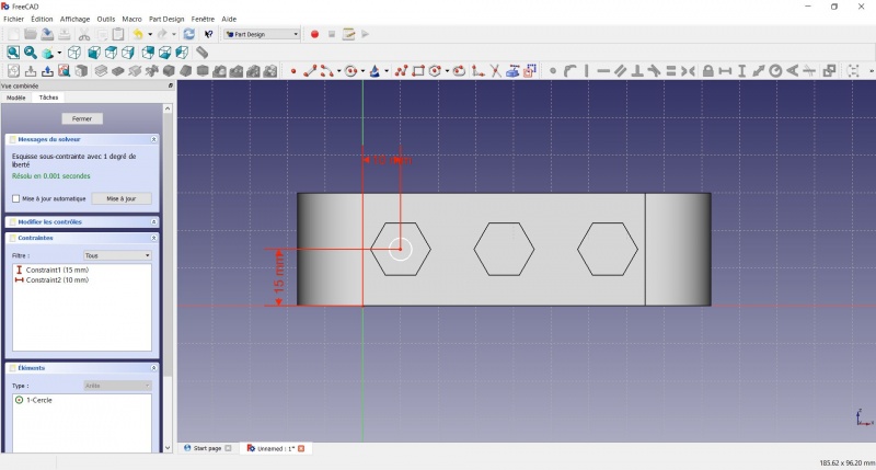
- Click on the center of the hexagon
- Click on the vertical of the XY plane
- Click on Distance
- A dialog prompts you to set a dimension. Enter 10mm, click OK.
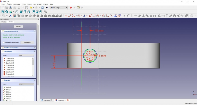
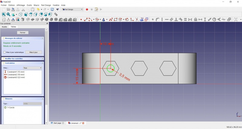
- Click on the blue circle of the hexagon
- Click on Radius
- A dialog prompts you to set a dimension. Enter 8mm, click OK.
- To leave the sketch, click either on the "Close" button on the left, or the icon in the toolbar, or press ESC.
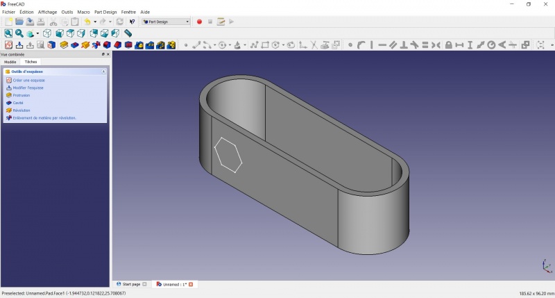
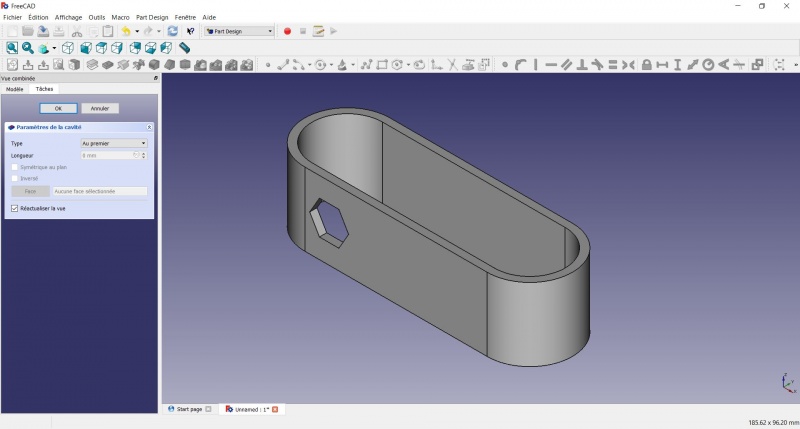
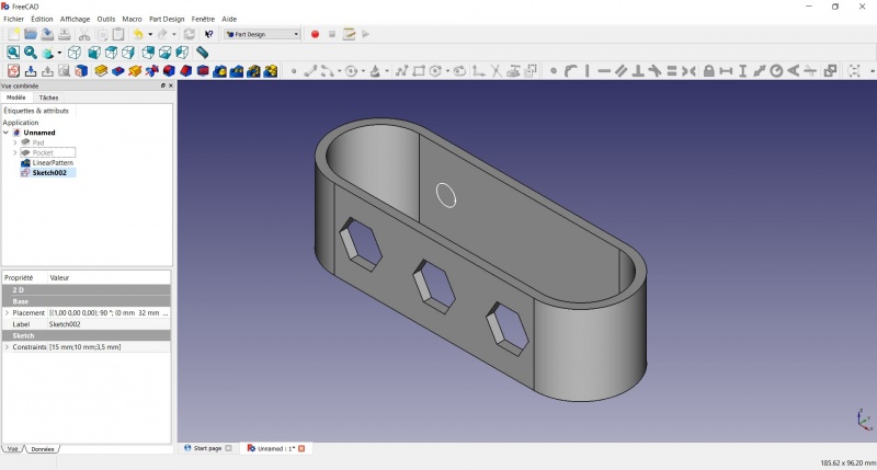
Create a hole
- Click on Axonometric among the standard views, to better see what will happen.
- Click on
 Pocket.
 - Select to the first in the dropdown menu and click OK.
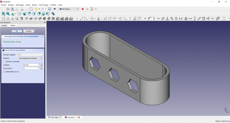
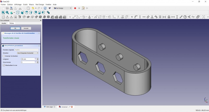
Linear repetition
- In the Combo View on the left, select the tree view instead of the contextual task menu, click on the pocket feature.
- Click on
 LinearPattern.
 - Set the length at 55mm and occurencies at 3, then click OK.
Create a sketch on it
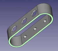
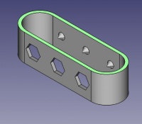
- Select the inner face
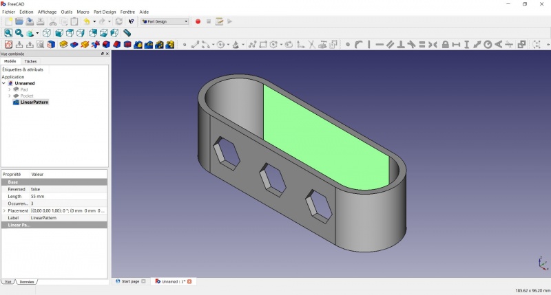
- Create a New sketch. As a face was selected it will not ask you to choose a plane.

- Click on Circle, click to place the center, move the pointer and click to define the radius.
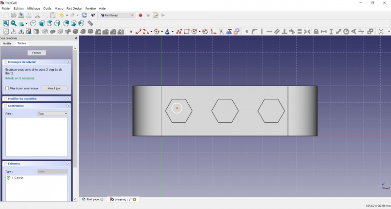
- Click on the center of the circle
- Click on the horizontal line of the XY plane
- Click on Distance
- A dialog prompts you to set a dimension. Enter 15mm, click OK.
- Click on the center of the circle
- Click on the vertical of the XY plane
- Click on Distance
- A dialog prompts you to set a dimension. Enter 10mm, click OK.
- Click on the circle
- Click on Radius
- A dialog prompts you to set a dimension. Enter 3.5mm, click OK.
- To leave the sketch, click either on the "Close" button on the left, or the icon in the toolbar, or press ESC.
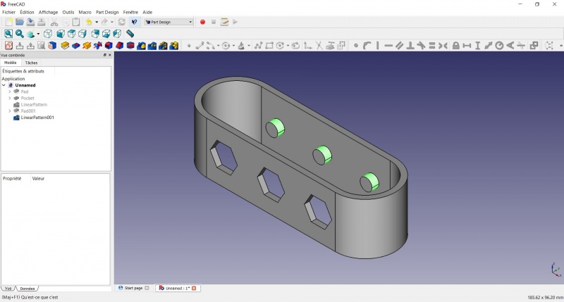
Create a pad
- Click on Axonometric among the standard views, to better see what will happen.
- Click on Pad.
- Enter 4mm and click OK.

Linear repetition
- In the Combo View on the left, select the tree view instead of the contextual task menu, click on the pad feature.
- Click on LinearPattern.
- Set the length at 55mm and occurencies at 3, then click OK.
Draft
- Select the side of each round pads
- Click on
 Draft.
 - Set the draft angle at 40°.
- Click on "Neutral plane" and select the face on which the sketch is drawn.
- Tick "Invert the draft direction".
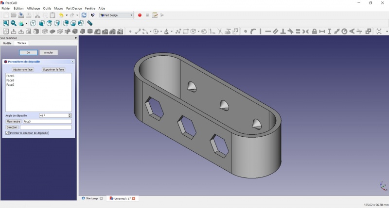
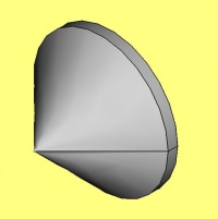
We could have used a chamfer to do something similar, but the draft is more appropriate in this case.
Chamfer = left / Draft = right
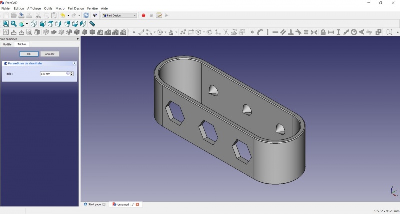
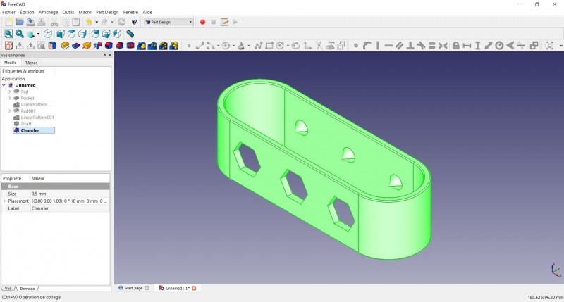
Finishes
- Holding CTRL select the bottom and top faces.
- Add a Chamfer of 0,5mm.
- Add a
Perfect!
Export as a .STL
- In the Combo View on the left, select the tree view instead of the contextual task menu, click on the last feature (the chamfer).
- Now you can select "Export..." from the File menu at the top left, and select the file format .STL.
- Print it instead of the first version or to replace it if it eventually broke ;-)
Questa pagina è recuperata da https://wiki.freecad.org/Toothbrush_Head_Stand