| Tema |
|---|
| Modeling |
| Nivel |
| Beginner |
| Tiempo para completar |
| 1 hour |
| Autores |
| EmmanuelG |
| Versión de FreeCAD |
| 0.16 or greater |
| Archivos de ejemplos |
| Thingiverse 2403310 |
| Ver también |
| None |
Un problema de la vida diaria
Los cepillos de dientes eléctricos rara vez vienen con un soporte para el cabezal, mientras que en una familia a menudo se ven varios cabezales utilizados con un solo cuerpo. Muchas personas que se enfrentan a un problema común nos llevan a una variedad de soluciones, como se puede ver en Thingiverse (200-800 proyectos están relacionados con eso). Aquí está la primera respuesta y cómo diseñarla.
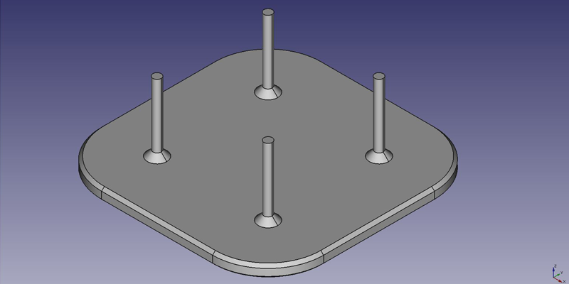
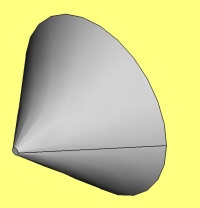
Este tutorial le llevará a través de los pasos necesarios para modelar la pieza que se muestra en la imagen de abajo utilizando las herramientas básicas del Ambiente de trabajo DiseñoPiezas. (muchas de las herramientas y capacidades no están cubiertas).
First idea : a plate
Primera idea : una placa
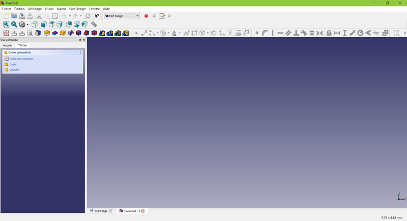
- Desde la página de inicio, seleccione
 DiseñoPieza, o crea un nuevo documento y selecciona el ambiente de trabajo DiseñoPieza.
Create a sketch
Crear un croquis
- Haz clic en
 Nuevo croquis. Ya sea desde el menú contextual de tareas de la izquierda, o desde la barra de herramientas de arriba o desde el menú Diseño Pieza de la parte superior.
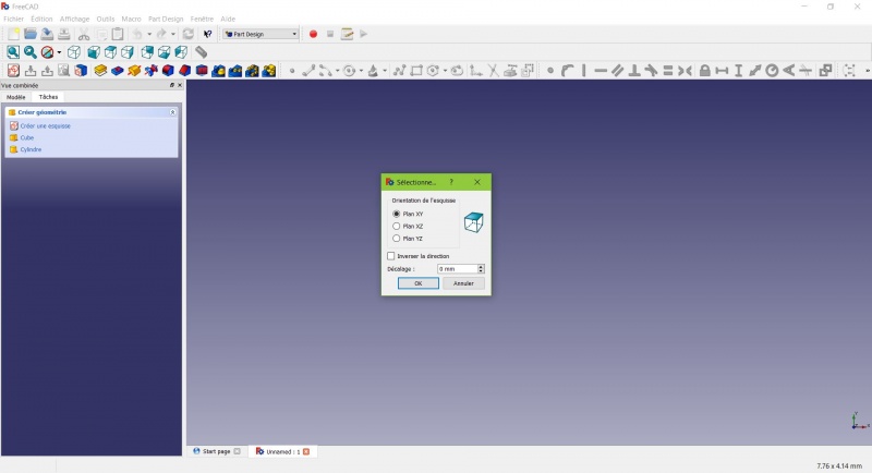
Un cuadro de diálogo le pide que elija la orientación del croquis y que proporcione un desplazamiento.
- Elegiremos el Plano XY como se muestra en la imagen de arriba (esa orientación corresponde a la placa de construcción común de la mayoría de las impresoras 3D), luego haz clic en OK.
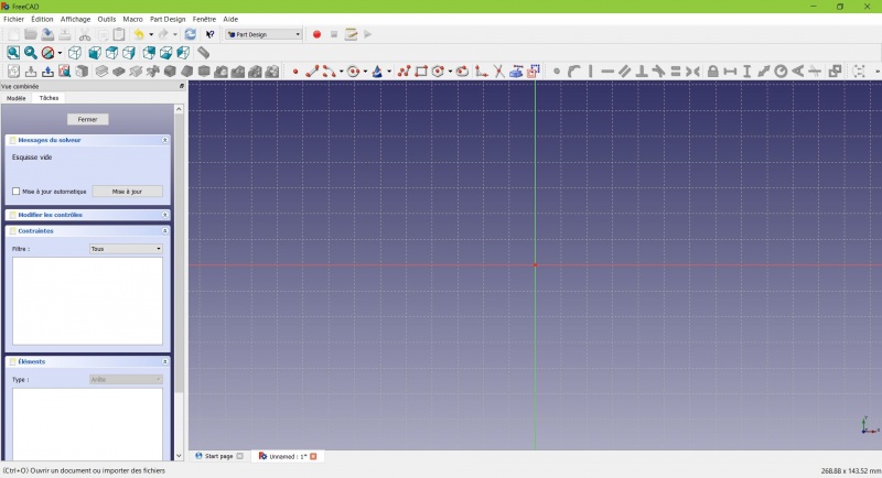
Ahora se encuentra frente al plano XY desde arriba, y tiene acceso a las herramientas de dibujo.
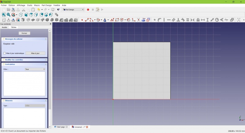
- Haz clic en
 Rectangle.
 - Haz clic para colocar un primer punto.
- Haz clic para colocar la esquina opuesta.
- Pulsa ESC o haz clic con el botón derecho del ratón para dejar de usar la herramienta.
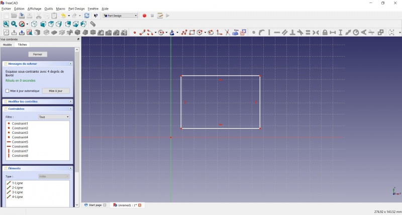
Ahora tiene un rectángulo flotante de dimensiones no especificadas.
- Haga clic en una línea del rectángulo, ahora tiene acceso a las herramientas de restricción a la derecha de la barra de herramientas (dependiendo del tamaño de su pantalla puede que tenga que arrastrarlas a la izquierda para verlas todas)
- Haga clic en
 Distancia
 - Un diálogo le pide que establezca una dimensión. Insertar 80mm, haga clic en OK.
- Repite con el otro lado del rectángulo, también 80mm.
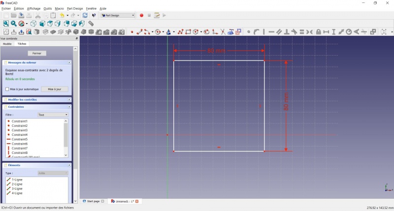
Ahora tienes un cuadrado flotante.
- Haga clic en el punto inferior izquierdo del cuadrado.
- Haga clic en el origen del plano XY (en la intersección de las dos líneas gruesas).
- Haga clic en
 Coincidente.
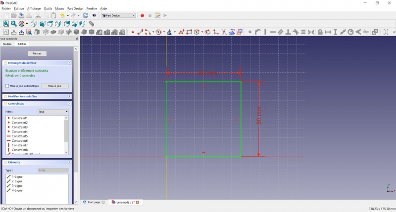
Ahora tiene un boceto totalmente restringido, como le indica el solucionador de la izquierda y el cambio de color. Es una buena práctica tener siempre un croquis totalmente restringido.
Un boceto poco restringido puede dejar espacio para cambios no deseados, si se modifica algo más tarde. Por el contrario, un croquis con demasiadas restricciones tampoco es bueno. En ese caso, el solucionador le advierte de las restricciones redundantes y debe eliminar algunas de ellas.
On the opposite, an over-constrained sketch is also not good. In that case the solver warn you of redundant constraints and you should remove some of them.
- To leave the sketch, click either on the "Close" button on the left, or the
 icon in the toolbar, or press ESC.
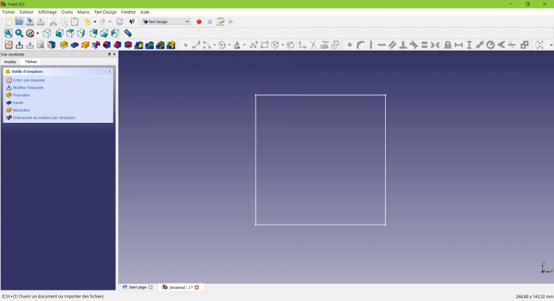
You now only see the square, and the contextual task menu on the left show you more options than before.
Create a pad
Crear una pastilla
- Haga clic en
 Axonométrico entre las vistas estándar, para ver mejor lo que ocurrirá.
 - Haga clic en
 Pastilla.
 - Introduzca 4mm y haga clic en OK.
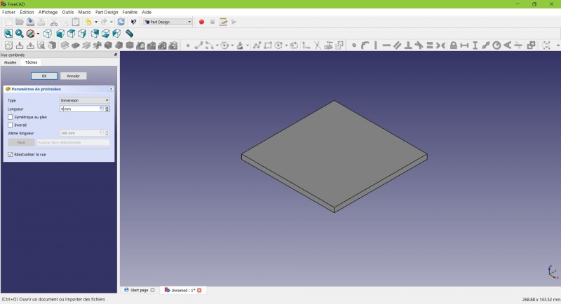
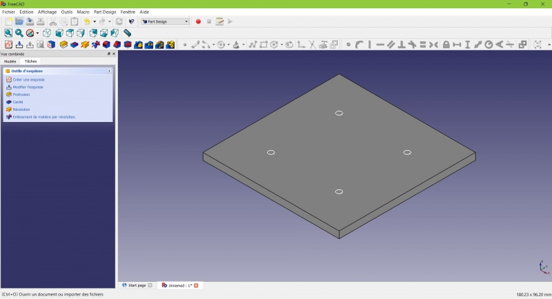
Your sketch is now in volume!
Create a sketch on it
Crear un croquis en él
- Selecciona la cara superior
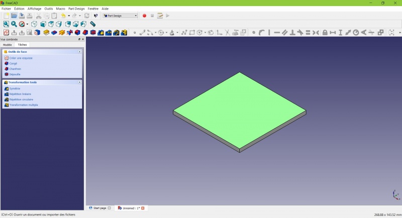
The color of the face change and you have more options in the contextual task menu.
- Click on New sketch. As a face was selected it will not ask you to choose a plane.
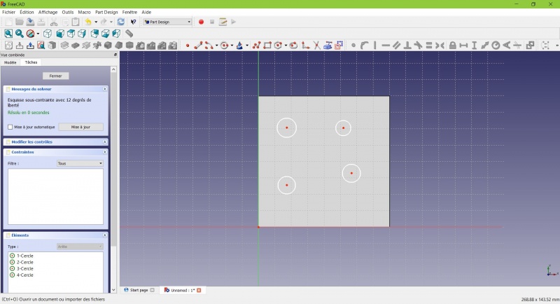
- Click on
 Circle, click to place the center, move the pointer and click to define the radius.
 - Draw 4 circles on the pad (of any size)
- Press ESC or click the right mouse button to stop using the tool.
- Select the circles
- Click on
 Equal Length
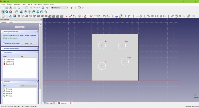
Now the circles share the same radius.
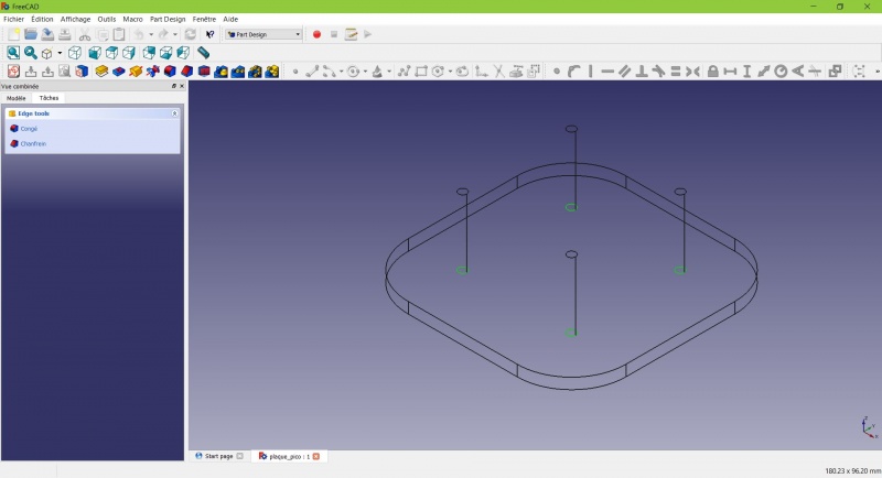
- Click on
 External geometry.
 - Click on the four sides of the square, it add lines, color magenta.
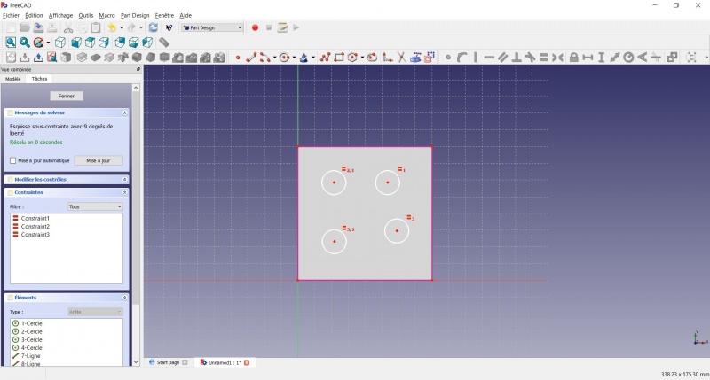
Theses lines will serve as reference to position the circles.
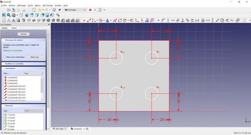
- Click on Distance.
- Click on a center of a circle.
- Click on a magenta line.
- Set distance (20mm from each side).
- Click on a circle
- Click on
 Radius and set it at 1,5mm.
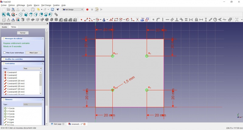
- To leave the sketch, click either on the "Close" button on the left, or the icon in the toolbar, or press ESC.
Create a pad
Crear una pastilla
- Haga clic en Axonométrico entre las vistas estándar, para ver mejor lo que ocurrirá.
- Haga clic en Pastilla.
- Insertar 25mm y haga clic en OK.
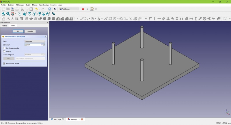
You have the basic shape, it just need final touches.
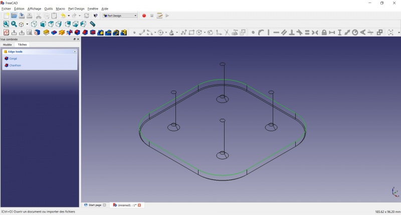
Rounding the corners
- Holding CTRL click on the vertical edge at each corner to select the four of them.
Don't hesitate to help you by switching the display mode (just at the left of the Axonometric View) between ![]() Wireframe and
Wireframe and ![]() Wireframe and shadow.
Wireframe and shadow.
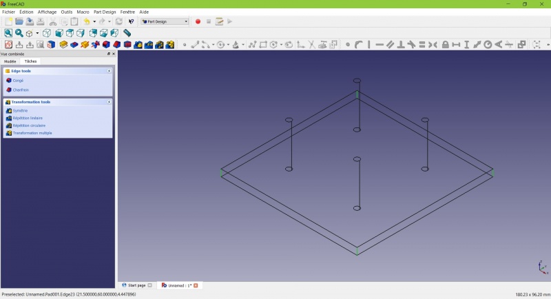
- Click on
 Fillet.
 - Set the radius at 20mm.
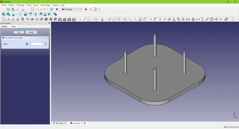
Much better.
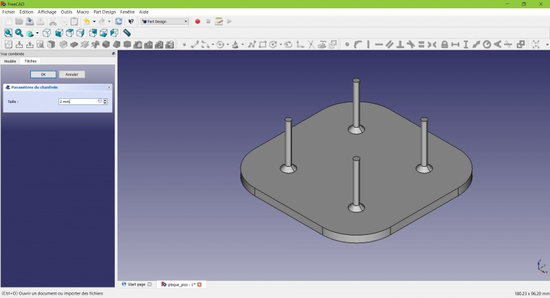
Making it more robust
We need to add material at the base of the cylinders to make them less prone to snap. Because of the printing orientation these small surfaces will be fragile at the junction with the base.
- Select the circles at the base of the cylinders
- Click on
 Chamfer.
 - Set it to 2mm.
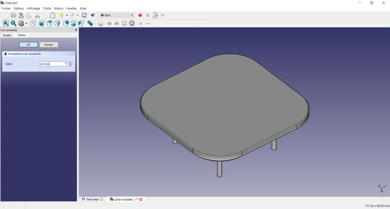
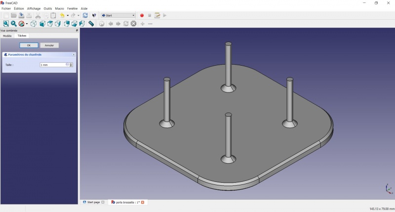
Chamfer the edges
- Select the face under the base, add a Chamfer of 0,5mm.
The first layer of plastic is often being squashed a little too much, this will compensate that and save you time in cleaning the model. If the first layer is ok that will make it only nicer
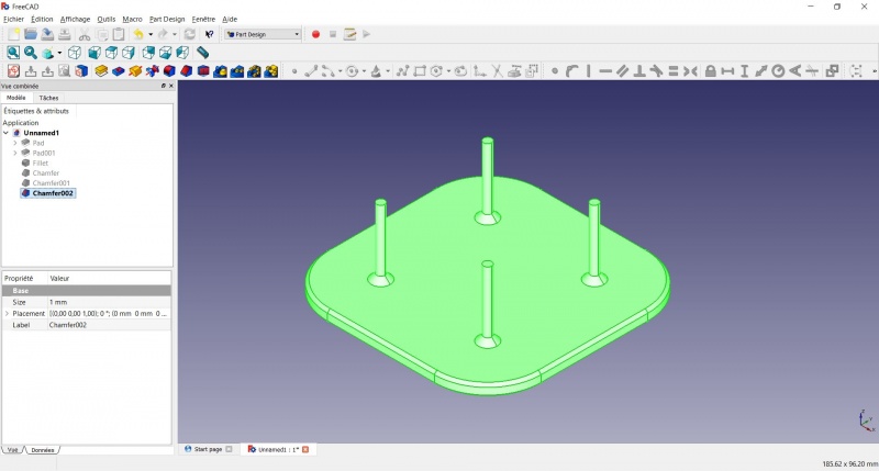
- Select the edges at the border of the upper face (holding CTRL ).
- Add a Chamfer of 1mm. This one is only aesthetic.
Tadaa!
Export as a .STL
- In the Combo View on the left, select the tree view instead of the contextual task menu, click on the last feature (the chamfer).
- Now you can select "Export..." from the File menu at the top left, and select the file format .STL.
- Just print it :-)
Inspiration
Inspiración
El modelo anterior es un buen punto de partida para utilizar FreeCAD, pero como soporte de cabezal de cepillo de dientes tiene sus defectos: debido a la orientación de la impresión y a la pequeña superficie los palos son propensos a romperse.
Inspired by the variety of solutions other people came up with, we will make this second version which will be much better.
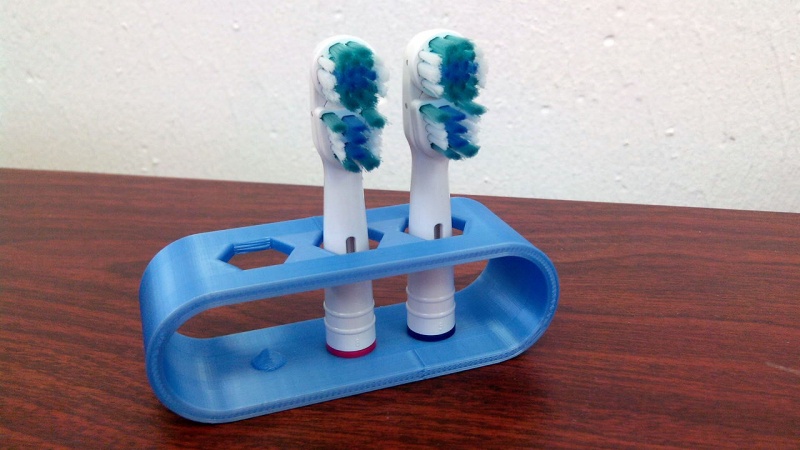
Don't worry it is often needed to go through several revision for an idea (e.g. : once the prototype on the picture was used, we added more space between the heads so that they should not touch).
In this second part you will also learn to use more tools, like the powerful Linear repetition.
Second idea : a band
- Create a new document and select the Part Design workbench.
Create a sketch
- Create a New sketch, on the XY plane.
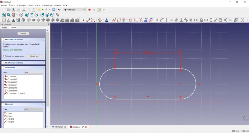
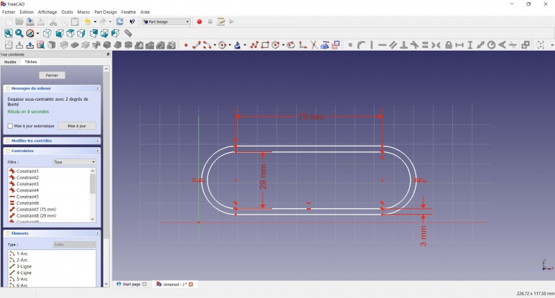
- Draw a
 Slot
Slot
- Click to place the first center
- Move to define the length and radius
- Click to set the second center.
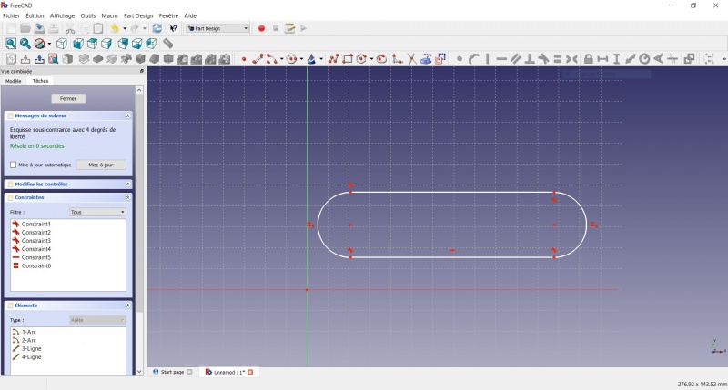
You now have a floating slot of unspecified dimensions.
- Click on one of the horizontal lines of the slot
- Click on Distance
- A dialog prompts you to set a dimension. Enter 75mm, click OK.
- that's for a 3 head stand, count 25mm for each, if you want more
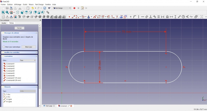
- Click on one point of the horizontal line
- Click on one point of the other horizontal line
- Click on Distance
- A dialog prompts you to set a dimension. Enter 29mm, click OK.
- Draw a Slot around the first slot.
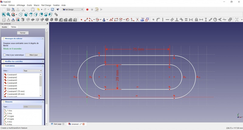
- Make the centers of the second slot coincident with the centers of the first slot with Coincident.
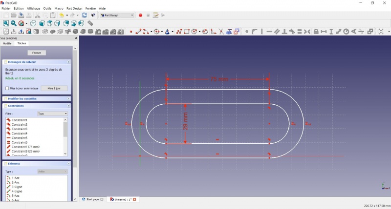
- Click on one point of the horizontal line of the first slot
- Click on one point of the nearest horizontal line of the second slot
- Click on Distance
- A dialog prompts you to set a dimension. Enter 3mm, click OK.
- To make the sketch fully constrained
- Click on the lower left point of the second slot
- Click on the origin of the XY plan
- Click on Coincident
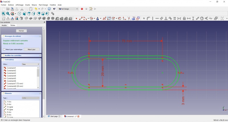
- To leave the sketch, click either on the "Close" button on the left, or the icon in the toolbar, or press ESC.
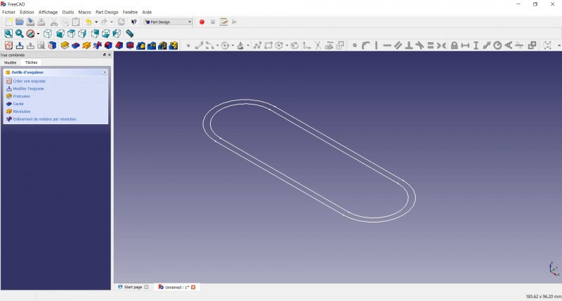
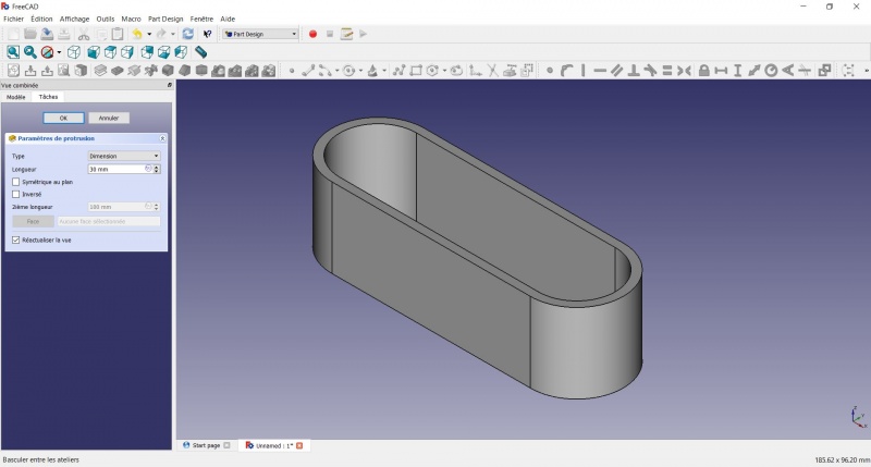
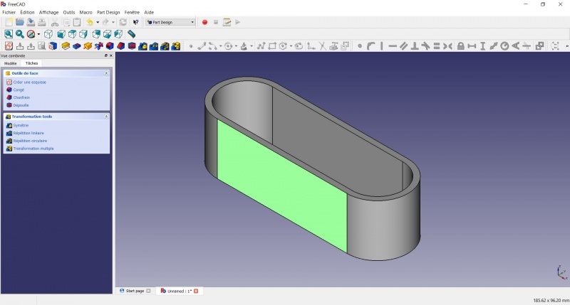
Create a pad
- Click on Axonometric among the standard views, to better see what will happen.
- Click on Pad.
- Enter 30mm and click OK.
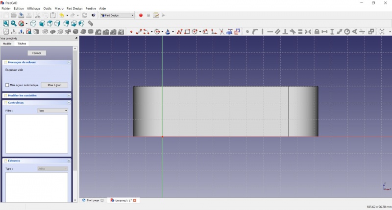
Create a sketch on it
- Select the upper face
- Create a New sketch. As a face was selected it will not ask you to choose a plane.
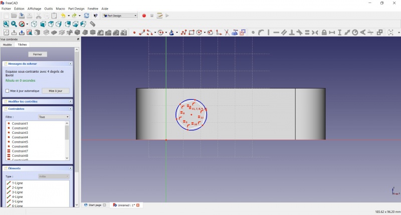
- Draw an
 Hexagon
- Click to place the center
- Move to define the radius
- Click to set
- Click on an edge of the hexagon
- Click on
 Horizontal
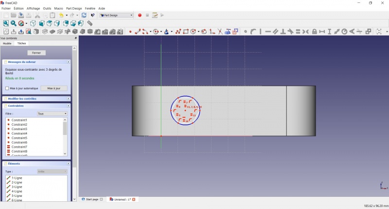
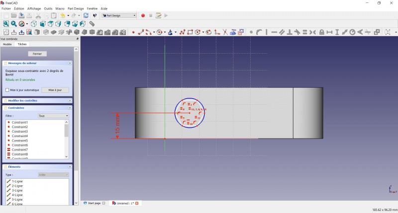
- Click on the center of the hexagon
- Click on the horizontal line of the XY plane
- Click on Distance
- A dialog prompts you to set a dimension. Enter 15mm, click OK.
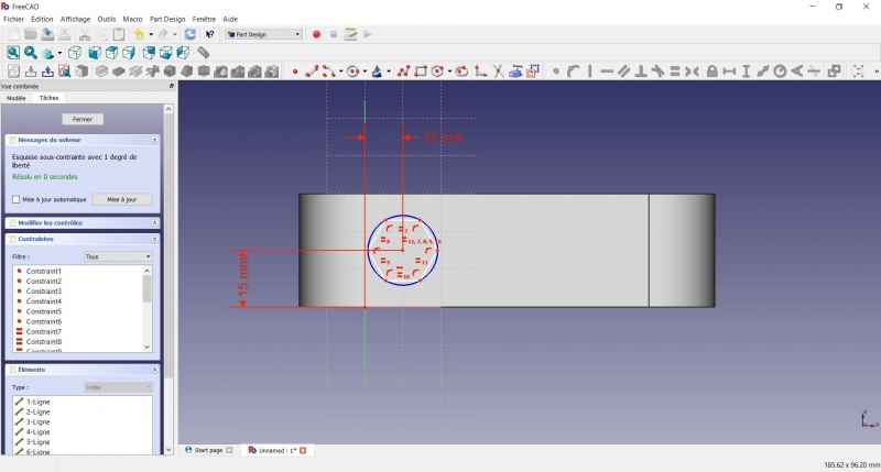
- Click on the center of the hexagon
- Click on the vertical of the XY plane
- Click on Distance
- A dialog prompts you to set a dimension. Enter 10mm, click OK.
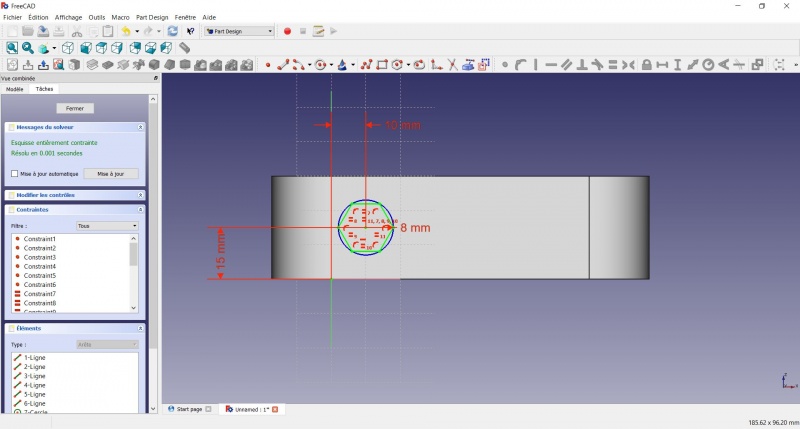
- Click on the blue circle of the hexagon
- Click on Radius
- A dialog prompts you to set a dimension. Enter 8mm, click OK.
- To leave the sketch, click either on the "Close" button on the left, or the icon in the toolbar, or press ESC.
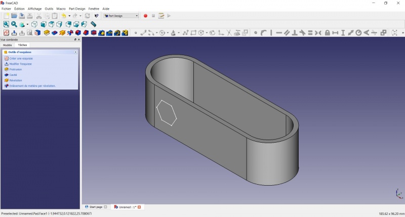
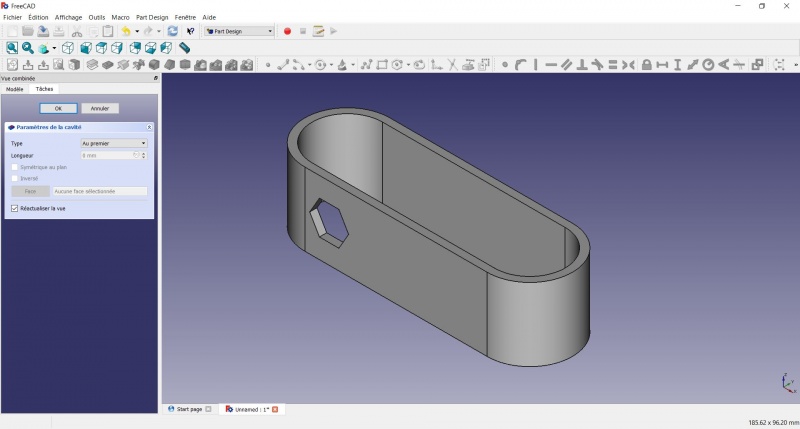
Create a hole
- Click on Axonometric among the standard views, to better see what will happen.
- Click on
 Pocket.
 - Select to the first in the dropdown menu and click OK.
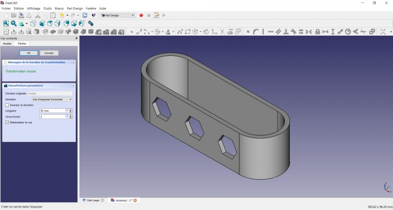
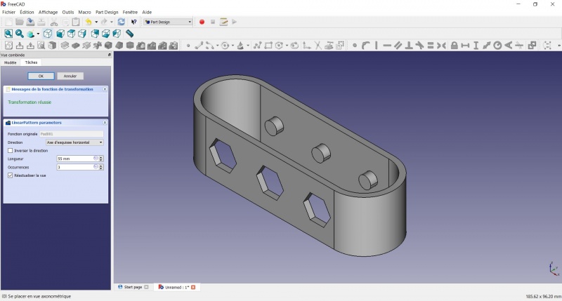
Linear repetition
- In the Combo View on the left, select the tree view instead of the contextual task menu, click on the pocket feature.
- Click on
 LinearPattern.
 - Set the length at 55mm and occurencies at 3, then click OK.
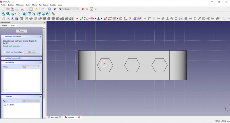
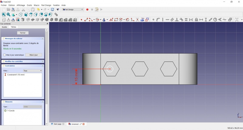
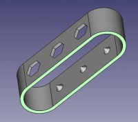
Create a sketch on it
- Select the inner face
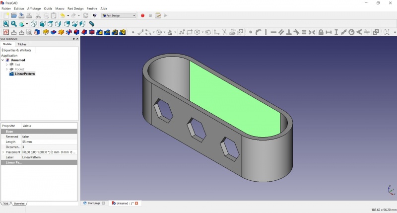
- Create a New sketch. As a face was selected it will not ask you to choose a plane.

- Click on Circle, click to place the center, move the pointer and click to define the radius.
- Click on the center of the circle
- Click on the horizontal line of the XY plane
- Click on Distance
- A dialog prompts you to set a dimension. Enter 15mm, click OK.
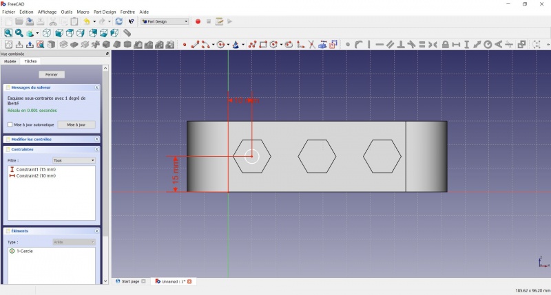
- Click on the center of the circle
- Click on the vertical of the XY plane
- Click on Distance
- A dialog prompts you to set a dimension. Enter 10mm, click OK.
- Click on the circle
- Click on Radius
- A dialog prompts you to set a dimension. Enter 3.5mm, click OK.
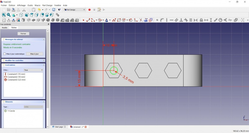
- To leave the sketch, click either on the "Close" button on the left, or the icon in the toolbar, or press ESC.
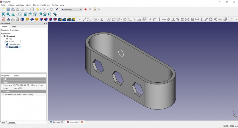
Create a pad
Crear una pastilla
- Haz clic en Axonométrico entre las vistas estándar, para ver mejor lo que ocurrirá.
- Haga clic en Pastilla.
- Insertar 4mm y haga clic en OK.

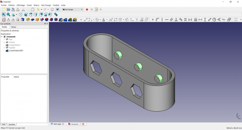
Linear repetition
- In the Combo View on the left, select the tree view instead of the contextual task menu, click on the pad feature.
- Click on LinearPattern.
- Set the length at 55mm and occurencies at 3, then click OK.
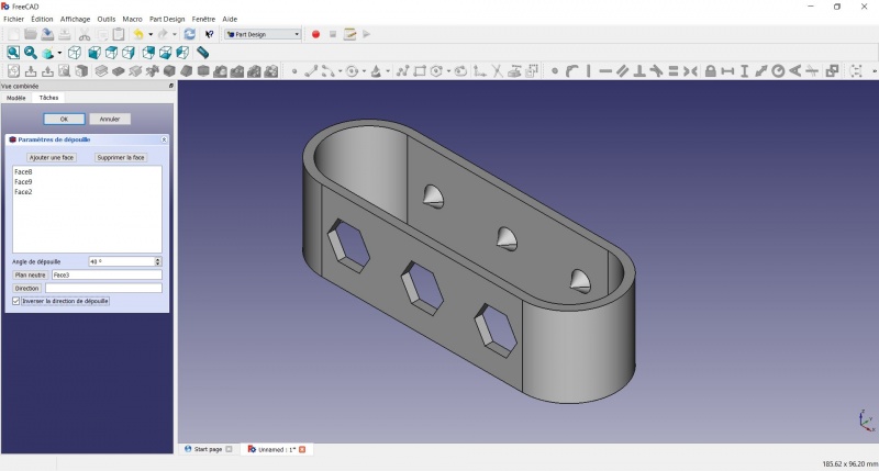
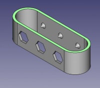
Draft
- Select the side of each round pads
- Click on
 Draft.
 - Set the draft angle at 40°.
- Click on "Neutral plane" and select the face on which the sketch is drawn.
- Tick "Invert the draft direction".
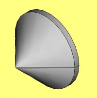
We could have used a chamfer to do something similar, but the draft is more appropriate in this case.
Chamfer = left / Draft = right
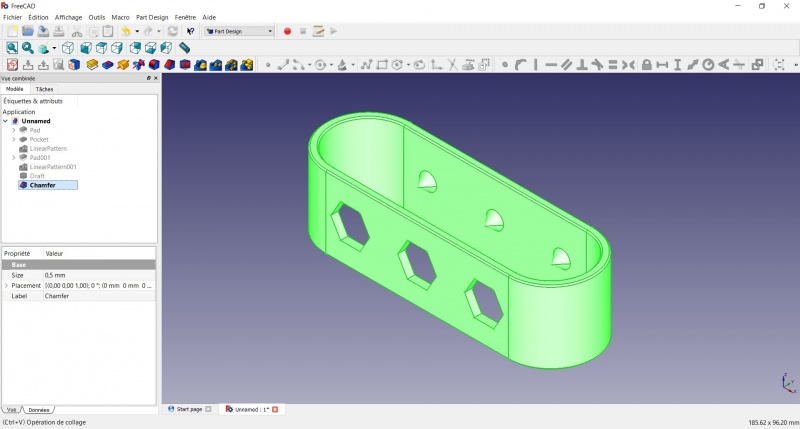
Finishes
- Holding CTRL select the bottom and top faces.
- Add a Chamfer of 0,5mm.
- Add a
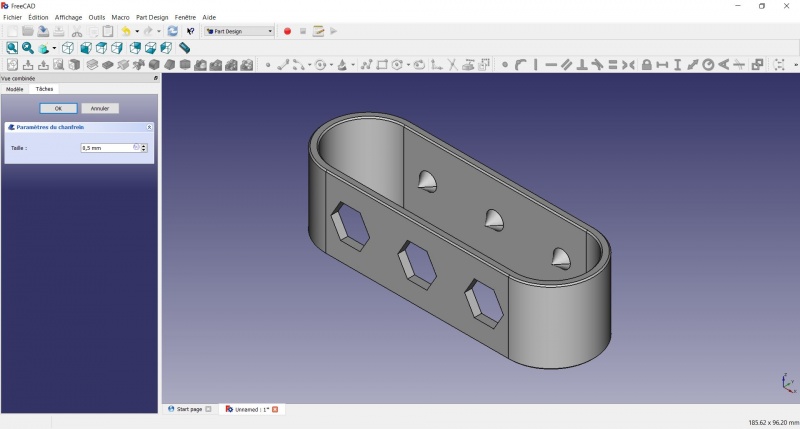
Perfect!
Export as a .STL
- In the Combo View on the left, select the tree view instead of the contextual task menu, click on the last feature (the chamfer).
- Now you can select "Export..." from the File menu at the top left, and select the file format .STL.
- Print it instead of the first version or to replace it if it eventually broke ;-)
Esta página ha sido recuperada de https://wiki.freecad.org/Toothbrush_Head_Stand