|
|
| Menu location |
|---|
| Surfaces → Gordon surface |
| Workbenches |
| Curves |
| Default shortcut |
| None |
| Introduced in version |
| - |
| See also |
| None |
Description
The ![]() Curves GordonSurface tool spans a surface on a grid of guide curves and profile curves.
Curves GordonSurface tool spans a surface on a grid of guide curves and profile curves.
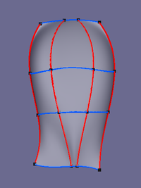
At least a frame of 2 guide curves and 2 profile curves is needed for a Gordon surface, additional curves in between allow for a more detailed control of its curvature.

![]()

A grid of 3 guides (yellow) and 4 profiles (purple) → A Gordon surface
Usage
- Select the lines that define the grid of the surface in the appropriate order:
- Select the guide curves (first direction) from one edge via the intermediate curves to the other edge.
- Select the profile curves (second direction) again from one edge via the intermediate curves to the other edge.
- There are several ways to invoke the tool:
- Press the
 Gordon surface button.
 - Select the Surfaces → Gordon surface option from the menu.
- Press the
- A Gordon object is created.
- Optionally edit the values in the Property editor to choose a different output type and adjust the related properties (see Properties below).
Notes
- Change the DataOutput property to
Wireframeto create a Gordon grid. It uses the same frame curves but may have different numbers of curves in between.- DataSamples U and DataSamples V properties determine the density of the grid in U and V direction accordingly.
- Samples equal the number of segments between the frame curves, 3 and 5 in this example:
![]()

Gordon surface → Gordon grid, the same object with Output property set to Wireframe
- The input curves of each group (guides and profiles) should touch all curves of the other group. In other words, they must form a grid or net pattern as shown here:
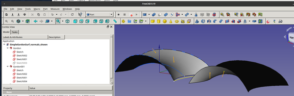
- In general, the surface normal of the resulting Gordon surface will be determined by the direction of the profiles.
- In this example, the surface on the left, the profiles were drawn from +Y to -Y and the resulting surface normal is +Z
- And on the right, the profiles are drawn from -Y to +Y, resulting in the surface normal oriented -Z.
- Part Extrude can be used to create a solid from the surface.
- PartDesign Pad can also create a solid from the surface. Dragging the surface into a Body creates a Base Feature that can then be padded.
Properties
See also: Property editor.
A Gordon object is derived from a Part Feature object and inherits all its properties. It also has the following additional properties:
Data
Base
- DataOutput (
Enumeration): Defines the output type:Surface(default): The result is a single Surface shape.Wireframe: The result is a grid of guide and profile curves.
Gordon
- DataMax Ctrl Pts (
Integer): Max Number of control points - DataSources (
LinkList): Curve network. User selected lines that are used to create the Gordon surface. - Data (Hidden)Tol2D (
Float): Parametric tolerance - DataTol3D (
Float): 3D tolerance
Surface
- DataFlip Normal (
Bool): Flip surface normal
Wireframe
- Data (Hidden)Samples U (
Integer): Number of samples in U direction. - Data (Hidden)Samples V (
Integer): Number of samples in V direction.
This page is retrieved from https://wiki.freecad.org/Curves_GordonSurface