| Topic |
|---|
| Robot Workbench |
| Level |
| Intermediate |
| Time to complete |
| Authors |
| FreeCAD version |
| Example files |
| See also |
| None |
Overview
This tutorial explains how to use FreeCAD and the ![]() Robot Simulation Workbench to simulate the motions of 6-axis serial robot. The tutorial focuses on the creation of the VRML file used as visualization. The base of the VRML file is a FreeCAD model. The version of FreeCAD used is 0.11.4252ppa1 on Ubuntu 32bit.
Robot Simulation Workbench to simulate the motions of 6-axis serial robot. The tutorial focuses on the creation of the VRML file used as visualization. The base of the VRML file is a FreeCAD model. The version of FreeCAD used is 0.11.4252ppa1 on Ubuntu 32bit.
Open a file or create one with FreeCAD
The tutorial is based on a STEP-file of a Stäubli TX40 (TX40-HB.stp). You can download the file from Stäubli. However, though I still didn't have time to check this, the method should also apply to a model completely made in FreeCAD. After opening the file, you should obtain this:
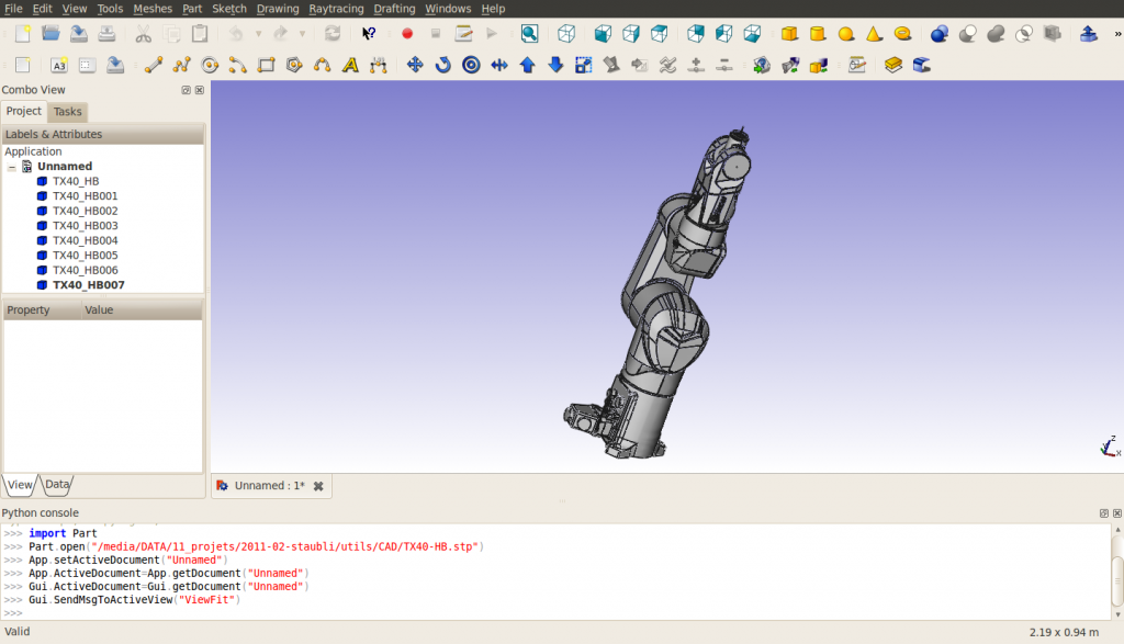
Notice, that on import, the robot is made of 8 shapes, directly on the root of the document tree. The structure of the exported VRML file may change if groups are used. The shapes are ordered from the base to the tool. The last shape contains the axes of rotations of all robot axes. The correlation shape name – part name is given by (as for now (March 2011) FreeCAD doesn't import the names included in STEP files):
| FreeCAD name | STEP name |
|---|---|
| TX40_HB | HORIZONTAL BASE CABLE OUTLET |
| TX40_HB001 | SHOULDER |
| TX40_HB002 | ARM |
| TX40_HB003 | ELBOW |
| TX40_HB004 | FOREARM |
| TX40_HB005 | WRIST |
| TX40_HB006 | TOOL FLANGE |
| TX40_HB007 | ? |
For this import, change the “Display Mode” of each shape, TX40_HB007 excepted, from “Flat Lines” to “Shaded” for the VRML export to look good. I also changed the colors to [245, 196, 0] and [204, 204, 204] to better correspond to Stäubli's yellow. Hide TX40_HB007 because it contains the axes of all joints and cannot be taken apart.
Measure geometric characteristics
In order to build the Denavit-Hartenberg table (see Robot 6-Axis) and prepare the vrml file, you need to get characteristics of the robot. For now, the measurement tool of FreeCAD is not ready, you can use the axes included in TX40_HB007 (the co-ordinates are indicated on the bottom left when you point an object with the mouse) or you have to use the Python console to get some information about the geometry. Note that the DH-table is only required if you need to use the inverse kinematics, i.e. get the Cartesian coordinates or drive the robot with Cartesian coordinates. The DH-table for this robot is the following (mm, deg and deg/s):
| i | d | θ | r | α | θmin | θmax | Axis velocity |
|---|---|---|---|---|---|---|---|
| 1 | 320 | q1 | 0 | -90 | -180 | 180 | 555 |
| 2 | 35 | q2 - 90 | 225 | 0 | -125 | 125 | 475 |
| 3 | 0 | q3 + 90 | 0 | 90 | -138 | 138 | 585 |
| 4 | 225 | q4 | 0 | -90 | -270 | 270 | 1035 |
| 5 | 0 | q5 | 0 | 90 | -120 | 133.5 | 1135 |
| 6 | 65 | q6 | 0 | 0 | -270 | 270 | 1575 |
The csv file is then:
a  , alpha, d  , theta, rotDir, maxAngle, minAngle, AxisVelocity
0  ,   -90, 320,     0,      1,      180,     -180, 555
225,     0,  35,   -90,      1,      125,     -125, 475
0  ,    90,   0,    90,      1,      138,     -138, 585
0  ,   -90, 225,     0,      1,      270,     -270, 1035
0  ,    90,   0,     0,      1,    133.5,     -120, 1135
0  ,     0,  65,     0,      1,      270,     -270, 1575
Export to VRML
Export the document to a VRML file. The structure of the VRML file is the following:
#VRML V2.0 utf8


Group {
  children
    Group {
      children [
        Group {
        …

        },

        Group {
        …

        },

        Group {
        …

        },

        Group {
        …

        },

        Group {
        …

        },

        Group {
        …

        },

        Group {
        …

        },

        Group {
        …

        } ]

    }

}
You can notice that we have 8 independent groups corresponding to the 8 shapes.
Preparation of the vrml file
All shapes in the VRML file are expressed in the base frame, independently from each other. For the Robot Simulation Workbench, we need to create a structure where a movement of a shape induces a movement of all shapes situated afterwards in the structure. The placement of the shapes will be relative to the preceding shape, so we need to include some translations from the absolute reference system to the relative one. The translations are described in the following picture:
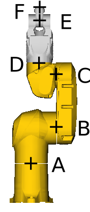
With
- A=(0, 0, 168)
- B=(0, 107.8, 320)
- C=(0, 104.15, 545)
- D=(0, 35, 601)
- E=(0, 35, 770)
- F=(0, 35, 835).
Let's take the example of axis 4 between ELBOW and FOREARM, situated at D=(xd, yd, zd). The anchor for the FreeCAD axis is
"DEF FREECAD_AXIS4 Transform { rotation 0 1 0 0 children ["
This corresponds to a rotation about the y-axis. In the CAD model, the rotation is about the z-axis. Thus, we need to a rotation about the x-axis of before the FreeCAD axis definition and of after it. Also, a translation of (-xd, -yd, -zd) is needed just before the Group corresponding to the definition of FOREARM to express it in the relative reference frame centered at D. This means that a translation of (xd, yd, zd) must be inserted before the first rotation.
At the end, the VRML file from the definition of ELBOW to the definition of FOREARM looks like this:
      # ELBOW
      Group {
        … here comes the unmodified definition of ELBOW

      },

      Transform {
        translation 0 35 601
        rotation 1 0 0 1.5707963
        children
          DEF FREECAD_AXIS4 Transform { rotation 0 1 0 0 children
            Transform {
              rotation 1 0 0 -1.5707963
              children
                Transform {
                  translation 0 -35 -601
                  children [
      # FOREARM
      Group {
        ... here comes the unmodified definition of FOREARM

      },
At the end of the document, the appropriate closing brackets must be inserted: ]}}}},
for each of the 6 axes. Eventually, the document looks like this (I don't know if I can link the file here because of copyrights):
#VRML V2.0 utf8


Group {
  children
  Group {
    children [
      # HORIZONTAL BASE CABLE OUTLET
      Group {
          ... here comes the unmodified definition of HORIZONTAL BASE CABLE OUTLET

      },

      Transform {
        translation 0 0 168
        rotation 1 0 0 1.5707963
        children
          DEF FREECAD_AXIS1 Transform { rotation 0 1 0 0 children
            Transform {
              rotation 1 0 0 -1.5707963
              children
                Transform {
                  translation 0 0 -168
                  children [
      # SHOULDER
      Group {
          ... here comes the unmodified definition of SHOULDER

      },

      Transform {
        translation 0 107.8 320
        #rotation 0 0 1 0
        children
          DEF FREECAD_AXIS2 Transform { rotation 0 1 0 0 children
            Transform {
              #rotation 0 0 1 0
              children
                Transform {
                  translation 0 -107.8 -320
                  children [
      # ARM
      Group {
          ... here comes the unmodified definition of ARM

      },

      Transform {
        translation 0 104.15 545
        #rotation 0 0 1 0
        children
          DEF FREECAD_AXIS3 Transform { rotation 0 1 0 0 children
            Transform {
              #rotation 0 0 1 0
              children
                Transform {
                  translation 0 -104.15 -545
                  children [
      # ELBOW
      Group {
          ... here comes the unmodified definition of ELBOW

      },

      Transform {
        translation 0 35 601
        rotation 1 0 0 1.5707963
        children
          DEF FREECAD_AXIS4 Transform { rotation 0 1 0 0 children
            Transform {
              rotation 1 0 0 -1.5707963
              children
                Transform {
                  translation 0 -35 -601
                  children [
      # FOREARM
      Group {
          ... here comes the unmodified definition of FOREARM

      },

      Transform {
        translation 0 35 770
        #rotation 0 0 1 0
        children
          DEF FREECAD_AXIS5 Transform { rotation 0 1 0 0 children
            Transform {
              #rotation 0 0 1 0
              children
                Transform {
                  translation 0 -35 -770
                  children [
      # WRIST
      Group {
          ... here comes the unmodified definition of WRIST

      },

      Transform {
        translation 0 35 835
        rotation 1 0 0 1.5707963
        children
          DEF FREECAD_AXIS6 Transform { rotation 0 1 0 0 children
            Transform {
              rotation 1 0 0 -1.5707963
              children
                Transform {
                  translation 0 -35 -835
                  children [
      # TOOL FLANGE
      Group {
          ... here comes the unmodified definition of TOOL FRAME

      },

      Group {
          ... here comes the unmodified definition of TX40_HB007

      } # "]" was deleted from this line
    ]}}}},
    ]}}}},
    ]}}}},
    ]}}}},
    ]}}}},
    ]}}}},
    ] # this is the "]" deleted from the line above
  }
}
Here is a patch to obtain the VRML file suitable for robot simulation:
7a8
>         # HORIZONTAL BASE CABLE OUTLET
95968a95970,95981
>         Transform {
>           translation 0 0 168
>           rotation 1 0 0 1.5707963
>           children
>             DEF FREECAD_AXIS1 Transform { rotation 0 1 0 0 children
>               Transform {
>                 rotation 1 0 0 -1.5707963
>                 children
>                   Transform {
>                     translation 0 0 -168
>                     children [
>         # SHOULDER
128428a128442,128453
>         Transform {
>           translation 0 107.8 320
>           #rotation 0 0 1 0
>           children
>             DEF FREECAD_AXIS2 Transform { rotation 0 1 0 0 children
>               Transform {
>                 #rotation 0 0 1 0
>                 children
>                   Transform {
>                     translation 0 -107.8 -320
>                     children [
>         # ARM
206503a206529,206540
>         Transform {
>           translation 0 104.15 545
>           #rotation 0 0 1 0
>           children
>             DEF FREECAD_AXIS3 Transform { rotation 0 1 0 0 children
>               Transform {
>                 #rotation 0 0 1 0
>                 children
>                   Transform {
>                     translation 0 -104.15 -545
>                     children [
>         # ELBOW
267111a267149,267160
>         Transform {
>           translation 0 35 601
>           rotation 1 0 0 1.5707963
>           children
>             DEF FREECAD_AXIS4 Transform { rotation 0 1 0 0 children
>               Transform {
>                 rotation 1 0 0 -1.5707963
>                 children
>                   Transform {
>                     translation 0 -35 -601
>                     children [
>         # FOREARM
417854a417904,417915
>         Transform {
>           translation 0 35 770
>           #rotation 0 0 1 0
>           children
>             DEF FREECAD_AXIS5 Transform { rotation 0 1 0 0 children
>               Transform {
>                 #rotation 0 0 1 0
>                 children
>                   Transform {
>                     translation 0 -35 -770
>                     children [
>         # WRIST
422053a422115,422126
>         Transform {
>           translation 0 35 835
>           rotation 1 0 0 1.5707963
>           children
>             DEF FREECAD_AXIS6 Transform { rotation 0 1 0 0 children
>               Transform {
>                 rotation 1 0 0 -1.5707963
>                 children
>                   Transform {
>                     translation 0 -35 -835
>                     children [
>         # TOOL FLANGE
435627c435700,435707
<         } ]
---
>         }
>       ]}}}},
>       ]}}}},
>       ]}}}},
>       ]}}}},
>       ]}}}},
>       ]}}}},
>       ]
Denna sida hämtas från https://wiki.freecad.org/VRML_Preparation_for_Robot_Simulation