| Argomento |
|---|
| Robot |
| Livello di difficoltà |
| Intermedio |
| Tempo di esecuzione |
| Autori |
| Versione di FreeCAD |
| Files di esempio |
| Vedere anche |
| Nessuno |
Overview
Questo tutorial spiega come utilizzare FreeCAD e l'ambiente Simulazione Robot per simulare i movimenti dei robot a 6 assi.
Il tutorial si concentra sulla creazione del file VRML utilizzato per la visualizzazione.
La base del file VRML è un modello di FreeCAD.
La versione di FreeCAD utilizzata è la 0.11.4252ppa1 in Ubuntu 32 bit.
Aprire un file o crearne uno con FreeCAD
Il tutorial si basa su un file STEP di un robot Stäubli TX40 (TX40-HB.stp).
È possibile scaricare il file file TX40-HB.stp da Stäubli.
Anche se non ho ancora avuto tempo di controllare, il metodo dovrebbe valere anche per un modello realizzato completamente in FreeCAD.
Dopo aver aperto il file, si dovrebbe ottenere questo:
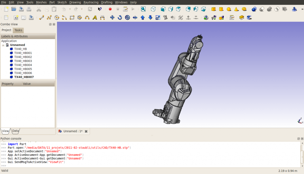
Notare che, nell'importazione, il robot è composto di 8 forme, direttamente sulla radice dell'albero del documento.
La struttura del file VRML esportato può cambiare se sono utilizzati i gruppi. Le forme sono ordinate a partire dalla base allo strumento.
L'ultima forma contiene gli assi di rotazione di tutti gli assi del robot.
I nomi delle forme sono attribuiti in modo correlativo da FreeCAD, (dato che per ora (marzo 2011) FreeCAD non importa i nomi inclusi nei file STEP):
| nome FreeCAD | nome STEP |
|---|---|
| TX40_HB | HORIZONTAL BASE CABLE OUTLET |
| TX40_HB001 | SHOULDER |
| TX40_HB002 | ARM |
| TX40_HB003 | ELBOW |
| TX40_HB004 | FOREARM |
| TX40_HB005 | WRIST |
| TX40_HB006 | TOOL FLANGE |
| TX40_HB007 | ? |
In questa importazione, cambiare la modalità di visualizzazione, “Display Mode”, di ogni forma, ad eccezione di TX40_HB007, da "Flat Lines" a "Shaded" per dare un buon aspetto all'esportazione VRML. Ho anche cambiato i colori in [245, 196, 0] e [204, 204, 204] per farli corrispondere meglio al giallo di Stäubli.
Nascondere TX40_HB007 perché contiene gli assi di tutti i giunti e non può essere smontato.
Misure delle caratteristiche geometriche
Per costruire la tabella di Denavit-Hartenberg (vedere 6-Axis_Robot ) e per preparare il file VRML, è necessario ottenere le caratteristiche del Robot.
Per ora, lo strumento di misurazione di FreeCAD non è ancora pronto, è possibile utilizzare gli assi inclusi in TX40_HB007 (le coordinate sono indicate in basso a sinistra quando si punta un oggetto con il mouse), oppure si deve utilizzare la console Python per ottenere delle informazioni sulla geometria.
Notare che la Tabella DH è necessaria solo quando si ha bisogno di usare la cinematica inversa, ad esempio, per ottenere le coordinate cartesiane o guidare il robot con coordinate cartesiane.
La Tabella DH per questo robot è la seguente (mm, gradi e gradi/s) :
| i | d | θ | r | α | θmin | θmax | Axis velocity |
|---|---|---|---|---|---|---|---|
| 1 | 320 | q1 | 0 | -90 | -180 | 180 | 555 |
| 2 | 35 | q2 - 90 | 225 | 0 | -125 | 125 | 475 |
| 3 | 0 | q3 + 90 | 0 | 90 | -138 | 138 | 585 |
| 4 | 225 | q4 | 0 | -90 | -270 | 270 | 1035 |
| 5 | 0 | q5 | 0 | 90 | -120 | 133.5 | 1135 |
| 6 | 65 | q6 | 0 | 0 | -270 | 270 | 1575 |
Il file csv è quindi:
 a  , alpha, d  , theta, rotDir, maxAngle, minAngle, AxisVelocity
0  ,   -90, 320,     0,      1,      180,     -180, 555
225,     0,  35,   -90,      1,      125,     -125, 475
0  ,    90,   0,    90,      1,      138,     -138, 585
0  ,   -90, 225,     0,      1,      270,     -270, 1035
0  ,    90,   0,     0,      1,    133.5,     -120, 1135
0  ,     0,  65,     0,      1,      270,     -270, 1575
Esportare in VRML
Esportare il documento in un file VRML. La struttura del file VRML è la seguente:
#VRML V2.0 utf8


Group {
  children
    Group {
      children [
        Group {
        …

        },

        Group {
        …

        },

        Group {
        …

        },

        Group {
        …

        },

        Group {
        …

        },

        Group {
        …

        },

        Group {
        …

        },

        Group {
        …

        } ]

    }

}
Si può notare che ci sono 8 gruppi indipendenti, corrispondenti alle 8 forme.
Preparazione del file VRML
Tutte le forme nel file VRML sono espresse nella struttura di base, indipendentemente le une dalle altre.
Per l'ambiente Simulazione Robot di FreeCAD, è necessario creare una struttura in cui un movimento di una forma induce un movimento di tutte le forme che sono situate successivamente nella struttura. Il posizionamento delle forme sarà relativo alla forma precedente, quindi è necessario includere alcune traduzioni dal sistema di riferimento assoluto a quello relativo.
Le traduzioni sono descritte nella figura seguente:
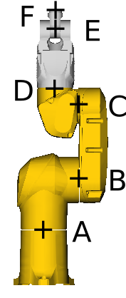
Con:
- A=(0, 0, 168)
- B=(0, 107.8, 320)
- C=(0, 104.15, 545)
- D=(0, 35, 601)
- E=(0, 35, 770)
- F=(0, 35, 835)
Prendiamo come esempio l'asse 4 tra ELBOW e FOREARM, situato in D=(xd, yd, zd). Il punto di ancoraggio per l'asse di FreeCAD è:
"DEF FREECAD_AXIS4 Transform { rotation 0 1 0 0 children ["
Questo corrisponde ad una rotazione intorno all'asse Y. Nel modello CAD, la rotazione è intorno all'asse Z.
Pertanto, è necessaria una rotazione intorno all'asse X di prima della definizione dell'asse di FreeCAD e di - dopo di essa.
Inoltre, è necessaria una translation di (-xd, yd-,-zd) immediatamente prima del gruppo corrispondente alla definizione di FOREARM e espressa nel frame di riferimento relativo centrato rispetto a D.
Ciò significa che la translation di (xd, yd, zd) deve essere inserita prima della prima rotazione.
Alla fine, il file VRML compreso tra la definizione di ELBOW e la definizione di FOREARM è simile al seguente:
      # ELBOW
      Group {
        … here comes the unmodified definition of ELBOW

      },

      Transform {
        translation 0 35 601
        rotation 1 0 0 1.5707963
        children
          DEF FREECAD_AXIS4 Transform { rotation 0 1 0 0 children
            Transform {
              rotation 1 0 0 -1.5707963
              children
                Transform {
                  translation 0 -35 -601
                  children [
      # FOREARM
      Group {
        ... here comes the unmodified definition of FOREARM

      },
Alla fine del documento, si devono inserire le parentesi di chiusura appropriate: ]}}}},
per ciascuno dei sei assi. Al termine, il documento si presenta così (non so se posso inserire un link al file a causa dei diritti d'autore):
#VRML V2.0 utf8


Group {
  children
  Group {
    children [
      # HORIZONTAL BASE CABLE OUTLET
      Group {
          ... here comes the unmodified definition of HORIZONTAL BASE CABLE OUTLET

      },

      Transform {
        translation 0 0 168
        rotation 1 0 0 1.5707963
        children
          DEF FREECAD_AXIS1 Transform { rotation 0 1 0 0 children
            Transform {
              rotation 1 0 0 -1.5707963
              children
                Transform {
                  translation 0 0 -168
                  children [
      # SHOULDER
      Group {
          ... here comes the unmodified definition of SHOULDER

      },

      Transform {
        translation 0 107.8 320
        #rotation 0 0 1 0
        children
          DEF FREECAD_AXIS2 Transform { rotation 0 1 0 0 children
            Transform {
              #rotation 0 0 1 0
              children
                Transform {
                  translation 0 -107.8 -320
                  children [
      # ARM
      Group {
          ... here comes the unmodified definition of ARM

      },

      Transform {
        translation 0 104.15 545
        #rotation 0 0 1 0
        children
          DEF FREECAD_AXIS3 Transform { rotation 0 1 0 0 children
            Transform {
              #rotation 0 0 1 0
              children
                Transform {
                  translation 0 -104.15 -545
                  children [
      # ELBOW
      Group {
          ... here comes the unmodified definition of ELBOW

      },

      Transform {
        translation 0 35 601
        rotation 1 0 0 1.5707963
        children
          DEF FREECAD_AXIS4 Transform { rotation 0 1 0 0 children
            Transform {
              rotation 1 0 0 -1.5707963
              children
                Transform {
                  translation 0 -35 -601
                  children [
      # FOREARM
      Group {
          ... here comes the unmodified definition of FOREARM

      },

      Transform {
        translation 0 35 770
        #rotation 0 0 1 0
        children
          DEF FREECAD_AXIS5 Transform { rotation 0 1 0 0 children
            Transform {
              #rotation 0 0 1 0
              children
                Transform {
                  translation 0 -35 -770
                  children [
      # WRIST
      Group {
          ... here comes the unmodified definition of WRIST

      },

      Transform {
        translation 0 35 835
        rotation 1 0 0 1.5707963
        children
          DEF FREECAD_AXIS6 Transform { rotation 0 1 0 0 children
            Transform {
              rotation 1 0 0 -1.5707963
              children
                Transform {
                  translation 0 -35 -835
                  children [
      # TOOL FLANGE
      Group {
          ... here comes the unmodified definition of TOOL FRAME

      },

      Group {
          ... here comes the unmodified definition of TX40_HB007

      } # "]" was deleted from this line
    ]}}}},
    ]}}}},
    ]}}}},
    ]}}}},
    ]}}}},
    ]}}}},
    ] # this is the "]" deleted from the line above
  }
}
Ecco un patch per ottenere il file VRML adatto per la simulazione del robot:
7a8
>         # HORIZONTAL BASE CABLE OUTLET
95968a95970,95981
>         Transform {
>           translation 0 0 168
>           rotation 1 0 0 1.5707963
>           children
>             DEF FREECAD_AXIS1 Transform { rotation 0 1 0 0 children
>               Transform {
>                 rotation 1 0 0 -1.5707963
>                 children
>                   Transform {
>                     translation 0 0 -168
>                     children [
>         # SHOULDER
128428a128442,128453
>         Transform {
>           translation 0 107.8 320
>           #rotation 0 0 1 0
>           children
>             DEF FREECAD_AXIS2 Transform { rotation 0 1 0 0 children
>               Transform {
>                 #rotation 0 0 1 0
>                 children
>                   Transform {
>                     translation 0 -107.8 -320
>                     children [
>         # ARM
206503a206529,206540
>         Transform {
>           translation 0 104.15 545
>           #rotation 0 0 1 0
>           children
>             DEF FREECAD_AXIS3 Transform { rotation 0 1 0 0 children
>               Transform {
>                 #rotation 0 0 1 0
>                 children
>                   Transform {
>                     translation 0 -104.15 -545
>                     children [
>         # ELBOW
267111a267149,267160
>         Transform {
>           translation 0 35 601
>           rotation 1 0 0 1.5707963
>           children
>             DEF FREECAD_AXIS4 Transform { rotation 0 1 0 0 children
>               Transform {
>                 rotation 1 0 0 -1.5707963
>                 children
>                   Transform {
>                     translation 0 -35 -601
>                     children [
>         # FOREARM
417854a417904,417915
>         Transform {
>           translation 0 35 770
>           #rotation 0 0 1 0
>           children
>             DEF FREECAD_AXIS5 Transform { rotation 0 1 0 0 children
>               Transform {
>                 #rotation 0 0 1 0
>                 children
>                   Transform {
>                     translation 0 -35 -770
>                     children [
>         # WRIST
422053a422115,422126
>         Transform {
>           translation 0 35 835
>           rotation 1 0 0 1.5707963
>           children
>             DEF FREECAD_AXIS6 Transform { rotation 0 1 0 0 children
>               Transform {
>                 rotation 1 0 0 -1.5707963
>                 children
>                   Transform {
>                     translation 0 -35 -835
>                     children [
>         # TOOL FLANGE
435627c435700,435707
<         } ]
---
>         }
>       ]}}}},
>       ]}}}},
>       ]}}}},
>       ]}}}},
>       ]}}}},
>       ]}}}},
>       ]
Questa pagina è recuperata da https://wiki.freecad.org/VRML_Preparation_for_Robot_Simulation