| Thème |
|---|
| Atelier Robot |
| Niveau |
| Intermediaire |
| Temps d'exécution estimé |
| Auteurs |
| Version de FreeCAD |
| 0.11.4252ppa1 |
| Fichiers exemples |
| Voir aussi |
| None |
Présentation
Ce tutoriel explique comment utiliser FreeCAD et l'![]() atelier de simulation Robot pour simuler les mouvements d'un robot série à 6 axes. Le tutoriel se concentre sur la création du fichier VRML utilisé comme visualisation. La base du fichier VRML est un modèle FreeCAD. La version de FreeCAD utilisée est 0.11.4252ppa1 sur Ubuntu 32bit.
atelier de simulation Robot pour simuler les mouvements d'un robot série à 6 axes. Le tutoriel se concentre sur la création du fichier VRML utilisé comme visualisation. La base du fichier VRML est un modèle FreeCAD. La version de FreeCAD utilisée est 0.11.4252ppa1 sur Ubuntu 32bit.
Ouvrir un fichier ou en créer un avec FreeCAD
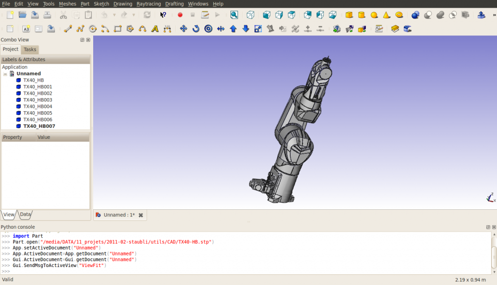
Ce tutoriel est basé sur un fichier STEP d'un Stäubli TX40 (TX40-HB.stp). Vous pouvez télécharger ce fichier à partir de Stäubli. Cependant, bien que je n'aie pas encore eu le temps de le vérifier, la méthode devrait également s'appliquer à un modèle entièrement réalisé dans FreeCAD. Après avoir ouvert le fichier, vous devriez obtenir ceci :
Remarquez, qu'à l'importation, le robot est composé de 8 formes, directement à la racine de l'arbre du document. La structure du fichier VRML exporté peut changer si des groupes sont utilisés. Les formes sont ordonnées de la base à l'outil. La dernière forme contient les axes de rotations de tous les axes du robot. La corrélation nom de forme - nom de pièce est donnée par (pour l'instant (mars 2011) FreeCAD n'importe pas les noms inclus dans les fichiers STEP) :
| Nom FreeCAD | Nom STEP |
|---|---|
| TX40_HB | HORIZONTAL BASE CABLE OUTLET |
| TX40_HB001 | SHOULDER |
| TX40_HB002 | ARM |
| TX40_HB003 | ELBOW |
| TX40_HB004 | FOREARM |
| TX40_HB005 | WRIST |
| TX40_HB006 | TOOL FLANGE |
| TX40_HB007 | ? |
Pour cette importation, changez le "Mode d'affichage" de chaque forme, à l'exception de TX40_HB007, de "Flat Lines" à "Shaded" pour que l'exportation VRML soit bonne. J'ai également changé les couleurs en [245, 196, 0] et [204, 204, 204] pour mieux correspondre au jaune de Stäubli. Cachez TX40_HB007 car il contient les axes de toutes les articulations et ne peut pas être démonté.
Mesurer les caractéristiques géométriques
Afin de construire la table de Denavit-Hartenberg (voir Robot 6 Axes) et de préparer le fichier VRML, vous devez obtenir les caractéristiques du robot. Pour l'instant, l'outil de mesure de FreeCAD n'est pas prêt, vous pouvez utiliser les axes inclus dans TX40_HB007 (les coordonnées sont indiquées en bas à gauche lorsque vous pointez un objet avec la souris) ou vous devez utiliser la console Python pour obtenir quelques informations sur la géométrie. Notez que la table DH n'est nécessaire que si vous devez utiliser la cinématique inverse, c'est-à-dire obtenir les coordonnées cartésiennes ou piloter le robot avec des coordonnées cartésiennes. La table DH pour ce robot est la suivante (mm, deg et deg/s) :
| i | d | θ | r | α | θmin | θmax | Vitesse de l'axe |
|---|---|---|---|---|---|---|---|
| 1 | 320 | q1 | 0 | -90 | -180 | 180 | 555 |
| 2 | 35 | q2 - 90 | 225 | 0 | -125 | 125 | 475 |
| 3 | 0 | q3 + 90 | 0 | 90 | -138 | 138 | 585 |
| 4 | 225 | q4 | 0 | -90 | -270 | 270 | 1035 |
| 5 | 0 | q5 | 0 | 90 | -120 | 133.5 | 1135 |
| 6 | 65 | q6 | 0 | 0 | -270 | 270 | 1575 |
Le fichier csv est alors :
a  , alpha, d  , theta, rotDir, maxAngle, minAngle, AxisVelocity
0  ,   -90, 320,     0,      1,      180,     -180, 555
225,     0,  35,   -90,      1,      125,     -125, 475
0  ,    90,   0,    90,      1,      138,     -138, 585
0  ,   -90, 225,     0,      1,      270,     -270, 1035
0  ,    90,   0,     0,      1,    133.5,     -120, 1135
0  ,     0,  65,     0,      1,      270,     -270, 1575
Exportation en VRML
Exportez le document vers un fichier VRML. La structure du fichier VRML est la suivante :
#VRML V2.0 utf8


Group {
  children
    Group {
      children [
        Group {
        …

        },

        Group {
        …

        },

        Group {
        …

        },

        Group {
        …

        },

        Group {
        …

        },

        Group {
        …

        },

        Group {
        …

        },

        Group {
        …

        } ]

    }

}
Vous pouvez remarquer que nous avons 8 groupes indépendants, correspondants aux 8 formes.
Préparation du fichier VRML
Toutes les formes du fichier VRML sont exprimées dans le cadre de base, indépendamment les unes des autres. Pour l'atelier de simulation Robot, nous devons créer une structure où le mouvement d'une forme induit un mouvement de toutes les formes situées après dans la structure. Le placement des formes sera relatif à la forme précédente, nous devons donc inclure des translations du système de référence absolu vers le système relatif. Ces translations sont décrites dans l'image suivante :
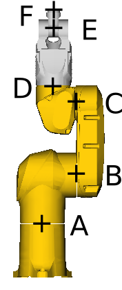
Avec
- A=(0, 0, 168)
- B=(0, 107.8, 320)
- C=(0, 104.15, 545)
- D=(0, 35, 601)
- E=(0, 35, 770)
- F=(0, 35, 835).
Prenons l'exemple de l'axe 4 entre ELBOW et FOREARM, situé à D=(xd, yd, zd). L'ancrage de l'axe FreeCAD est le suivant
"DEF FREECAD_AXIS4 Transform { rotation 0 1 0 0 children ["
Cela correspond à une rotation autour de l'axe des y. Dans le modèle CAO, la rotation se fait autour de l'axe z. Ainsi, nous avons besoin d'une rotation autour de l'axe des x de avant la définition de l'axe FreeCAD et de après celle-ci. De même, une translation de (-xd, -yd, -zd) est nécessaire juste avant le groupe correspondant à la définition de FOREARM pour l'exprimer dans le référentiel relatif centré sur D. Cela signifie qu'une translation de (xd, yd, zd) doit être insérée avant la première rotation. A la fin, le fichier VRML de la définition de ELBOW à la définition de FOREARM ressemble à ceci :
      # ELBOW
      Group {
        … here comes the unmodified definition of ELBOW

      },

      Transform {
        translation 0 35 601
        rotation 1 0 0 1.5707963
        children
          DEF FREECAD_AXIS4 Transform { rotation 0 1 0 0 children
            Transform {
              rotation 1 0 0 -1.5707963
              children
                Transform {
                  translation 0 -35 -601
                  children [
      # FOREARM
      Group {
        ... here comes the unmodified definition of FOREARM

      },
En fin de document, les crochets de fermeture appropriés doivent être insérés : ]}}}},
pour chacun des 6 axes. Finalement, le document ressemble à ceci (je ne sais pas si je peux lier le fichier ici à cause des droits d'auteur):
#VRML V2.0 utf8


Group {
  children
  Group {
    children [
      # HORIZONTAL BASE CABLE OUTLET
      Group {
          ... here comes the unmodified definition of HORIZONTAL BASE CABLE OUTLET

      },

      Transform {
        translation 0 0 168
        rotation 1 0 0 1.5707963
        children
          DEF FREECAD_AXIS1 Transform { rotation 0 1 0 0 children
            Transform {
              rotation 1 0 0 -1.5707963
              children
                Transform {
                  translation 0 0 -168
                  children [
      # SHOULDER
      Group {
          ... here comes the unmodified definition of SHOULDER

      },

      Transform {
        translation 0 107.8 320
        #rotation 0 0 1 0
        children
          DEF FREECAD_AXIS2 Transform { rotation 0 1 0 0 children
            Transform {
              #rotation 0 0 1 0
              children
                Transform {
                  translation 0 -107.8 -320
                  children [
      # ARM
      Group {
          ... here comes the unmodified definition of ARM

      },

      Transform {
        translation 0 104.15 545
        #rotation 0 0 1 0
        children
          DEF FREECAD_AXIS3 Transform { rotation 0 1 0 0 children
            Transform {
              #rotation 0 0 1 0
              children
                Transform {
                  translation 0 -104.15 -545
                  children [
      # ELBOW
      Group {
          ... here comes the unmodified definition of ELBOW

      },

      Transform {
        translation 0 35 601
        rotation 1 0 0 1.5707963
        children
          DEF FREECAD_AXIS4 Transform { rotation 0 1 0 0 children
            Transform {
              rotation 1 0 0 -1.5707963
              children
                Transform {
                  translation 0 -35 -601
                  children [
      # FOREARM
      Group {
          ... here comes the unmodified definition of FOREARM

      },

      Transform {
        translation 0 35 770
        #rotation 0 0 1 0
        children
          DEF FREECAD_AXIS5 Transform { rotation 0 1 0 0 children
            Transform {
              #rotation 0 0 1 0
              children
                Transform {
                  translation 0 -35 -770
                  children [
      # WRIST
      Group {
          ... here comes the unmodified definition of WRIST

      },

      Transform {
        translation 0 35 835
        rotation 1 0 0 1.5707963
        children
          DEF FREECAD_AXIS6 Transform { rotation 0 1 0 0 children
            Transform {
              rotation 1 0 0 -1.5707963
              children
                Transform {
                  translation 0 -35 -835
                  children [
      # TOOL FLANGE
      Group {
          ... here comes the unmodified definition of TOOL FRAME

      },

      Group {
          ... here comes the unmodified definition of TX40_HB007

      } # "]" was deleted from this line
    ]}}}},
    ]}}}},
    ]}}}},
    ]}}}},
    ]}}}},
    ]}}}},
    ] # this is the "]" deleted from the line above
  }
}
Voici un patch pour obtenir le fichier VRML adapté à la simulation de robot :
7a8
>         # HORIZONTAL BASE CABLE OUTLET
95968a95970,95981
>         Transform {
>           translation 0 0 168
>           rotation 1 0 0 1.5707963
>           children
>             DEF FREECAD_AXIS1 Transform { rotation 0 1 0 0 children
>               Transform {
>                 rotation 1 0 0 -1.5707963
>                 children
>                   Transform {
>                     translation 0 0 -168
>                     children [
>         # SHOULDER
128428a128442,128453
>         Transform {
>           translation 0 107.8 320
>           #rotation 0 0 1 0
>           children
>             DEF FREECAD_AXIS2 Transform { rotation 0 1 0 0 children
>               Transform {
>                 #rotation 0 0 1 0
>                 children
>                   Transform {
>                     translation 0 -107.8 -320
>                     children [
>         # ARM
206503a206529,206540
>         Transform {
>           translation 0 104.15 545
>           #rotation 0 0 1 0
>           children
>             DEF FREECAD_AXIS3 Transform { rotation 0 1 0 0 children
>               Transform {
>                 #rotation 0 0 1 0
>                 children
>                   Transform {
>                     translation 0 -104.15 -545
>                     children [
>         # ELBOW
267111a267149,267160
>         Transform {
>           translation 0 35 601
>           rotation 1 0 0 1.5707963
>           children
>             DEF FREECAD_AXIS4 Transform { rotation 0 1 0 0 children
>               Transform {
>                 rotation 1 0 0 -1.5707963
>                 children
>                   Transform {
>                     translation 0 -35 -601
>                     children [
>         # FOREARM
417854a417904,417915
>         Transform {
>           translation 0 35 770
>           #rotation 0 0 1 0
>           children
>             DEF FREECAD_AXIS5 Transform { rotation 0 1 0 0 children
>               Transform {
>                 #rotation 0 0 1 0
>                 children
>                   Transform {
>                     translation 0 -35 -770
>                     children [
>         # WRIST
422053a422115,422126
>         Transform {
>           translation 0 35 835
>           rotation 1 0 0 1.5707963
>           children
>             DEF FREECAD_AXIS6 Transform { rotation 0 1 0 0 children
>               Transform {
>                 rotation 1 0 0 -1.5707963
>                 children
>                   Transform {
>                     translation 0 -35 -835
>                     children [
>         # TOOL FLANGE
435627c435700,435707
<         } ]
---
>         }
>       ]}}}},
>       ]}}}},
>       ]}}}},
>       ]}}}},
>       ]}}}},
>       ]}}}},
>       ]
Cette page est extraite de https://wiki.freecad.org/VRML_Preparation_for_Robot_Simulation