|
기술도면 단면도 |
| Menu location |
|---|
| 기술도면 → 기술도면 보기 → 단면도 삽입 |
| Workbenches |
| 기술도면 작업대 |
| Default shortcut |
| None |
| Introduced in version |
| - |
| See also |
| 기술도면 복합단면, 기술도면 보기 |
설명
기술도면 단면도 도구는 기존의 부품 보기를 기반으로 단면도를 삽입합니다.


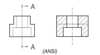
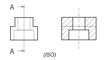
이미 배치된 보기를 단면하여 내부 구멍과 사선으로 채워진 절단면을 보여줍니다.
위 이미지는 ANSI 화살표 형식을 보여줍니다.
아래 이미지는 ISO 화살표 형식을 보여줍니다.
용법
- 3D보기 또는 나무 보기에서 단면할 부품의 보기를 선택하세요.
- 도구를 호출하는 방법은 여러 가지가 있습니다.
단면도 삽입 버튼을 누르세요.
- 메뉴에서 기술도면 → 기술도면 보기 →
단면도 삽입을 선택하세요.
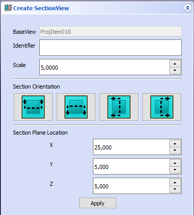
- 다양한 속성을 계산하는 데 도움이 되는 작업창이 열립니다. 단면보기 방향과 절단평면 위치에 대한 기본적인 값이 자동으로 설정되는데, 이 값은 사용자가 원하는 대로 변경할 수 있습니다.

보기의 절단면을 정의하는 작업창
속성
속성 편집기도 참고하세요.
In the properties of the 데이터Base View you can change the appearance of the section line.
A Section View, formally a TechDraw::DrawViewSection object, is derived from a Part View, formally a TechDraw::DrawViewPart object, and inherits all its properties. It also has the following additional properties:
Data
Appearance
- 데이터Section Line Stretch (
FloatConstraint): Adjusts the length of the section line.1.0is normal length,1.1would be 10% longer,0.9would be 10% shorter. introduced in 1.0
Cut Operation
- 데이터Fuse Before Cut (
Bool): Fuse the source shapes before performing the section cut. - 데이터Trim After Cut (
Bool): Additionally trim the resulting shape after the section cut to remove any unwanted pieces. introduced in 0.21 - 데이터Use Previous Cut (
Bool) Use the cut shape from the base view instead of the original object. introduced in 1.0
Cut Surface Format
- 데이터Cut Surface Display (
Enumeration): 절단면의 모양. 다음 중 선:Hide: 잘린 표면을 숨기고 윤곽선만 표시합니다.Color: 기술도면 환경 설정에서 설정된 절단 표면 색상을 사용하여 절단 표면의 색상을 지정합니다.SvgHatch: Hatches the section cut using a hatchPatHatch: Hatches the section cut using a geometric hatch
- 데이터File Hatch Pattern (
File): Full path to SVG hatch pattern file. - 데이터File Geom Pattern (
File): Full path to PAT pattern file. - 데이터Svg Included (
FileIncluded): SVG 해치 패턴 파일의 전체 경로. - 데이터Pat Included (
FileIncluded): PAT 패턴 파일의 전체 경로. - 데이터Name Geom Pattern (
String): Name of the PAT pattern to use. - 데이터Hatch Scale (
Float): 해치 패턴 배 조정 - 데이터Hatch Rotation (
Float): 해치 패턴을 시계 반대 방향으로 회전.0.21 버전부터 도입 - 데이터 (Hidden)Hatch Offset (
Vector): Hatch pattern offset. introduced in 0.21
Section
- 데이터Section Symbol (
String): The identifier for this section. - 데이터Base View (
Link): The view on which this section is based. - 데이터Section Normal (
Vector): A vector describing the direction normal to the cutting plane. - 데이터Section Origin (
Vector): A vector describing a point on the cutting plane. Typically the centroid of the original part. - 데이터Section Direction (
Enumeration): The direction in the Base View for this section. Options:Aligned,Right,Left,UporDown.
View
Cut Surface
- 보기Cut Surface Color (
Color): Solid color for surface highlight. Used if 데이터Cut Surface Display is set toColor. - 보기 (Hidden)Show Cut Surface (
Bool): Show/hide the cut surface.
Surface Hatch
- 보기Geom Hatch Color (
Color): The color of the Geometric hath pattern. - 보기Hatch Color (
Color): The color of the Svg hatch pattern. - 보기 (Hidden)Hatch Cut Surface (
Bool): Hatch the cut surface. - 보기Weight Pattern (
Float): Line weight of the Geometric hatch pattern.
보충 설명
- 단면선 형식: 두 가지 단면선 형식이 지원되며(위에 표시된 대로) 주석 탭의 기본 설정 "단면선 표준"에 의해 제어됩니다.
ANSI옵션은 "당기는 화살표"(일부 지역에서는 "전통 형식"이라고 함)를 사용하고,ISO옵션은 "밀어내는 화살표"(참조 화살표 형식이라고도 함)를 사용합니다. - Fuse Before Cut: the section operation sometimes fails to cut the source shapes. If Fuse Before Cut is true, the source shapes are merged into a single shape before the section operation is attempted. If you encounter problems with the section operation, try flipping this value.
- Trim After Cut: the section cut operation sometimes leaves behind a portion of the source shape. If Trim After Cut is true, an additional cut operation is performed on the result of the first cut which should remove any unwanted pieces.
- Cut Surface Display: the cut surface can be hidden, painted in a solid color, hatched using an Svg pattern (default) or hatched using a PAT pattern. See Hatching.
Scripting
See also: Autogenerated API documentation and FreeCAD Scripting Basics.
A SectionView can be created with macros and from the Python console by using the following functions:
doc = FreeCAD.ActiveDocument
box = doc.Box
page = doc.Page

view = doc.addObject("TechDraw::DrawViewPart", "View")
page.addView(view)
view.Source = box
view.Direction = (0, 0, 1)

section = doc.addObject("TechDraw::DrawViewSection", "Section")
page.addView(section)
section.Source = box
section.BaseView = view
section.Direction = (0, 1, 0)
section.SectionNormal = (-1, 0, 0)

doc.recompute()
예제
단면도와 일부 사용 사례에 대한 자세한 내용은 기술도면 단면 예제를 참조하세요.
![]()


이 페이지에서 인용한 것은 https://wiki.freecad.org/TechDraw_SectionView