This documentation is not finished. Please help and contribute documentation.
GuiCommand model explains how commands should be documented. Browse Category:UnfinishedDocu to see more incomplete pages like this one. See Category:Command Reference for all commands.
See WikiPages to learn about editing the wiki pages, and go to Help FreeCAD to learn about other ways in which you can contribute.
소개
![]() 기술도면 작업대는 단면도 생성과 관련하여 큰 진전을 이루었습니다. 참고 페이지를 너무 많이 채우지 않기 위해, 이 페이지에서는 수행되는 작업에 대한 예를 제공하고 적절한 이름을 제공하는 것이 목적입니다.
기술도면 작업대는 단면도 생성과 관련하여 큰 진전을 이루었습니다. 참고 페이지를 너무 많이 채우지 않기 위해, 이 페이지에서는 수행되는 작업에 대한 예를 제공하고 적절한 이름을 제공하는 것이 목적입니다.
저는 올바른 용어를 찾기 위해 최선을 다하고 있지만, 저는 영어 원어민이 아니기 때문에, 제 실수를 발견하면 여러분이 수정해 주셔야 합니다.
단면(Sections)
단면은 겉으로 보이지 않거나 어려운 물체 내부의 세부 사항을 보여주는 데 사용됩니다. 일반적으로 도면에는 최소한 2개 방향에서 물체를 보여주는 보기(예: 정면도, 평면도)가 있습니다. 단면이 제공되면 해당 위치와 방향은 보기 중 하나에 단면선으로 표시됩니다.
Example object
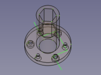
This object has no use at all except to describe the different section representations.
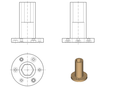
3 views and a 3D image of the object
Simple sections
The ![]() Insert Section View tool creates a simple section that uses a single plane to cut through an object.
Insert Section View tool creates a simple section that uses a single plane to cut through an object.
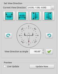
The tool requires a base view (데이터Base View property) to position the section plane. The vertical axis of the section plane is always the normal of the base view and the horizontal axis of the section plane is parallel to the section line. Usually the section view is oriented with its horizontal axis also parallel to the section line. The angle between section line and the base view's horizontal axis is controlled by widgets in the Set View Direction area of the tool's task panel:
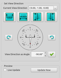
The View Direction as Angle combobox allows to set an arbitrary angle. The four buttons can be used to set predefined angles:
![]() 90° (up),
90° (up),
![]() 270° (down),
270° (down),
![]() 180° (left),
180° (left),
![]() 0° (right)
0° (right)
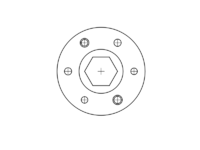
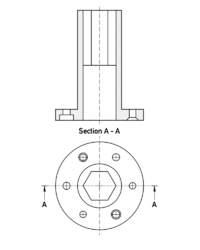
Horizontal section
Section A-A (section up)
![]()
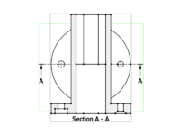
Base View + ![]() → Base View and Section A-A in its default position
→ Base View and Section A-A in its default position
Base View and Section A-A in its proper position.
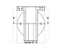
Section B-B (section down)
![]()
Base View + ![]() → Base View and Section B-B in its default position
→ Base View and Section B-B in its default position
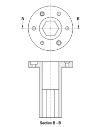
Base View and Section B-B in its proper position
Vertical section
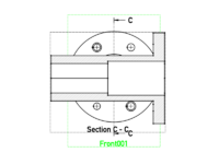
Section C-C (section left)
![]()
Base View + ![]() → Base View and Section C-C in its default position
→ Base View and Section C-C in its default position
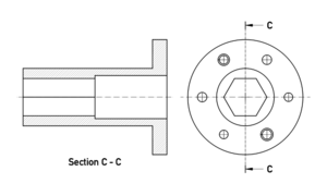
Base View and Section C-C in its proper position
Section D-D (section right)
![]()
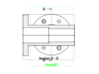
Base View + ![]() → Base View and Section D-D in its default position
→ Base View and Section D-D in its default position
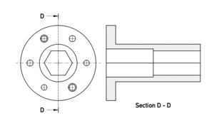
Base View and Section D-D in its proper position
Arbitrary section
Section E-E (section at an arbitrary angle)
![]()
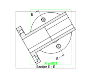
Base View + "View Direction as Angle" set to 30° → Base View and Section E-E in its default position
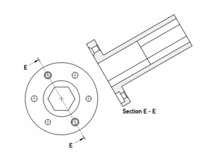
Base View and Section E-E in its proper position
By default the section plane goes through the bounding box center of the view (in this case coincident with the center of gravity of the object). To get an offset section we need to change the values in the Section Plane Location area.
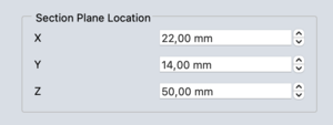
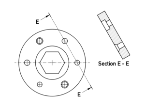
Here the section line was moved 22 mm in the X and 14 mm in the Y-direction (without proof that the line goes through the centers of the holes). The automatically generated Z value has no influence in this case.
Auxiliary view
FreeCAD lacks a tool to derive auxiliary views from a base view, but ![]() Insert Section View can also handle that:
Insert Section View can also handle that:
Using Section E-E from above and changing the mentioned values to X = 40 mm and Y = -23 mm the section no longer cuts the object and becomes an auxiliary view instead. Note: be careful when changing the values, large steps can crash FreeCAD!
![]()
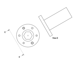
Section E-E like in the example above + moved section line/plane → View E
The label was edited. The section line and one arrow have to be hidden in following steps since a single arrow is enough to properly define an auxiliary view.
Notes
- Versions used:
- The examples have been created using weekly build 0.21 - 31155 with first angle and ISO selected.
- C-C, D-D, and E-E: The default Positions were updated to display the current default placement (weekly build 0.21 - 31709) (updated 2023-02-03).
- On this occasion I realized that horizontal and vertical center lines are oriented according to the page but not the view and so cannot be used to align base and section view, as I would expect.
- Applying an offset to a section line/plane is a bit complicated, because it can only be moved along global axes and not according to (local) view axes.
Simple sections in praxis
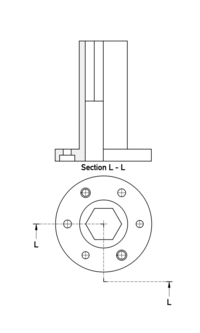
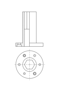
Single Section
If there is only one section view in the drawing, and it is plain to see that the object is cut along a center line, the section line, including the arrows, and the view title may be omitted.
Both drawings are to standard
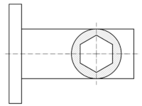
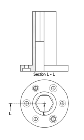
Internal section
A section view may be integrated into the base view. This case doesn't require arrows and a title either.
Complex sections
The ![]() Insert Complex Section tool creates a complex section, such as an aligned section or an offset section, that uses more than one plane to cut an object.
Insert Complex Section tool creates a complex section, such as an aligned section or an offset section, that uses more than one plane to cut an object.
The tool requires a base view (데이터Base View property) to place several connected section planes to cut through the object, these are defined by a 3D polyline. (This tool can also handle curves, but curved sections are rather unusual.)
The vertical axes of the section planes are always parallel to the normal of the base view. Their horizontal axes are derived from the related segments of the 3D polyline. The orientation of the Section view depends on one of the 3D polyline's segments and is influenced by the widgets in the Set View Direction area of the tool's task panel:
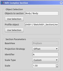
This tool provides 3 options in the Projection Strategy combobox to handle the section line segments:
Offset: only segments perpendicular to the view direction are displayed (default).Aligned: all segments are displayed in true length.NoParallel: all segments are projected along the same view direction. Depending on the angle between a segment and the view direction the projection may be shorter than the cut area. Segments parallel to the view direction result in a single line.
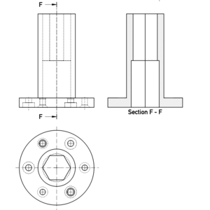
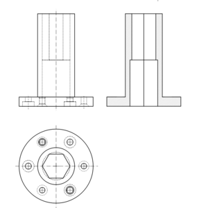
Offset section
An offset section starts with a base view plus a 3D polyline, a ![]() sketch in this case.
sketch in this case.
![]()
![]()
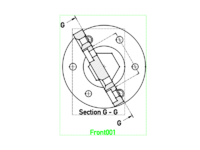
Base view + sketch + "Projection Strategy" set to Offset + "View Direction as Angle" set to 30° → Base View and Section G-G in its default position
The view direction angle must be set to a matching value to avoid unexpected results.
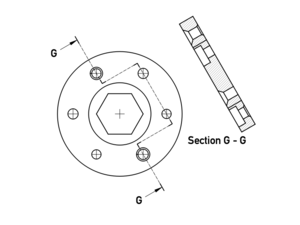
Base View and Section G-G in its proper position
Aligned section
An aligned section also starts with a base view and 3D polyline.
![]()
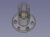
![]()
Base view + sketch + "Projection Strategy" set to Aligned + ![]() (or "View Direction as Angle" set to
(or "View Direction as Angle" set to 0°) → Base View and Section H-H in its default position
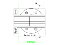
The view direction angle can be set with ![]() and
and ![]() for a coarse orientation. It has to be guessed and set to a best matching value or the result may be unexpected.
for a coarse orientation. It has to be guessed and set to a best matching value or the result may be unexpected.
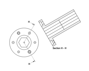
Base View and Section H-H if the "View Direction as Angle" is set to 30° (parallel to the lower segment of the section line). The section has been moved to its proper position
If the view direction angle is set incorrectly the result may look like this:
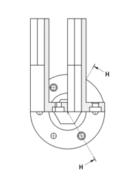
Arrows on either side of the section line result in a strange projection, "View Direction as Angle" is set to 90°
Auxiliary view
The ![]() Insert Complex Section tool can, like the
Insert Complex Section tool can, like the ![]() Insert Section View tool, create auxiliary views from base views:
Insert Section View tool, create auxiliary views from base views:
An auxiliary view starts with a base view and a single 3D line placed outside the object.
![]()
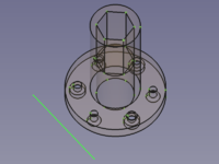
![]()
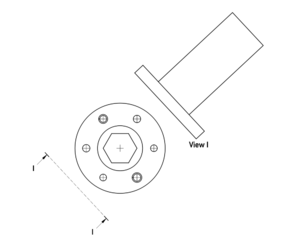
Base view + 3D line → View I
The View Direction as Angle value has to be extracted from the 3D line manually. The label was edited. The section line and one arrow have to be hidden in following steps since a single arrow is enough to properly define an auxiliary view.
NoParallel section
A NoParallel section is a mixture of aligned and offset sections.
![]()
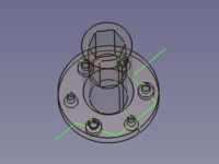
![]()
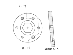
Base view + sketch → Base View and Section K-K rotated -85° and moved
The arrow direction should have been horizontal, but the tool did not work when the value of View Direction as Angle was set to 0°. So the sketch was rotated by 5° and said angle was set to 5° as well.
Comparison NoParallel vs. Offset and Aligned
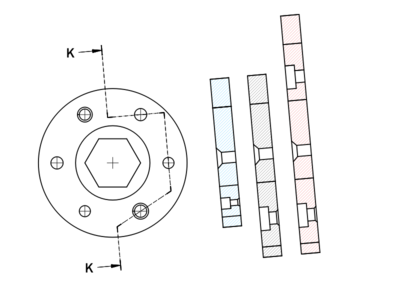
Base View and Section K-K in 3 versions: "Offset": blue hatching, "NoParallel": black hatching, "Aligned": red hatching
For some reason if the value of View Direction as Angle of the aligned section is set to exactly 5° the result is faulty. Only after editing the section and accepting the strange value of 5.14° that the angle is somehow set to, is the correct result displayed.
Same as above with "View Direction as Angle" set to 5° exactly: the view direction of the second segment from the top is flipped (the shaft is visible)
Complex one line sections
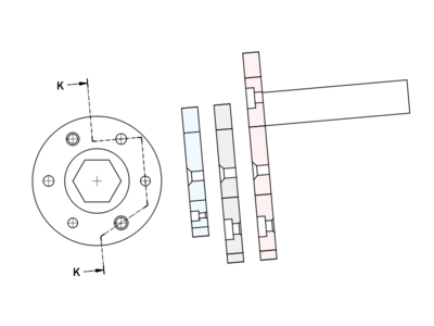
The length (width) of a complex section depends on the length of the used 3D line, but the results differ from offset section to NoParallel section:
Two sections based on the same 3D line.
Left: The Offset section shows the segment between the arrows as a section while the rest of the object stays uncut.
Right: The NoParallel section only shows the section between the arrows and omits the rest of the object.
Complex sections in praxis
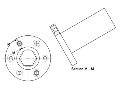
Half section
A view showing a symmetric object cut on one side of a center line and uncut on the other. The depth is usually defined by another center line.
Left and center: Offset section view with and without section line arrows and title, both are to standard.
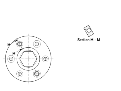
Right: Offset section view based on an alternative section line, see section M-M above.
Notes
- Versions used:
- The examples have been created using weekly build 0.21 - 31155 with first angle and ISO selected.
- Weekly build 0.21 - 31340 for M-M.
- The view direction (the orientation of the arrows) has to be determined manually.
- All complex sections have to be rotated manually.
- A View Direction as Angle value of
0°exactly does not work for offset sections. (180°, too?) - The View Direction as Angle will be reset to a strange value whenever a section view is activated for editing.
이 페이지에서 인용한 것은 https://wiki.freecad.org/TechDraw_Section_Examples