This documentation is not finished. Please help and contribute documentation.
GuiCommand model explains how commands should be documented. Browse Category:UnfinishedDocu to see more incomplete pages like this one. See Category:Command Reference for all commands.
See WikiPages to learn about editing the wiki pages, and go to Help FreeCAD to learn about other ways in which you can contribute.
|
|
| Posizione nel menu |
|---|
| SheetMetal → Relief |
| Ambiente |
| SheetMetal |
| Avvio veloce |
| None |
| Introdotto nella versione |
| - |
| Vedere anche |
| Nessuno |
Descrizione
Lo ![]() strumento SheetMetal Relief
strumento SheetMetal Relief
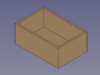
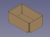
This command is the first of three steps to convert a shell object made with the Part Workbench or PartDesign Workbench into an unfoldable sheet metal object:
![]()
![]()
![]()
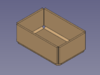

Creare uno scarico nell'angolo per la piegatura della lamiera.
Utilizzo
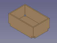
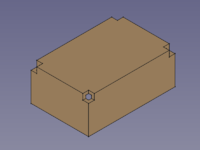
Per aggiungere uno scarico all'angolo della piega:
- Iniziare con una piastra di base o un foglio, selezionare un vertice d'angolo a cui applicare lo scarico
- Fare clic sullo strumento
 Relief per aggiungere un taglio di scarico all'angolo.
![]()
Notes
Nota: questo ambiente non dispone di uno strumento per creare una piastra di base, quindi è necessario avviare il modello con uno dei seguenti metodi:
- Metodo 1:
 Cubo di Part
 - Metodo 2: Un solido estruso realizzato con
 Estrudi di Part da un:
 Rettangolo di Draft o una
 Polilinea di Draft o uno
 Schizzo
- Usare
 Spessore di Part per creare un solido (Tipicamente con il valore dello spessore della lamiera.)
- Metodo 3:
 Corpo di PartDesign contenente un
 cubo additivo o un
 pad prodotto da uno schizzo.
- Usare Spessore di Part per creare un solido (Tipicamente con il valore dello spessore della lamiera.)
- Metodo 1:
Se si inizia con un corpo di PartDesign, è possibile combinare le funzioni di Sheet Metal con le funzioni di PartDesign come ![]() tasche o
tasche o ![]() fori.
fori.
Shell objects can be created with commands from the ![]() Part Workbench
or the
Part Workbench
or the ![]() PartDesign Workbench.
PartDesign Workbench.
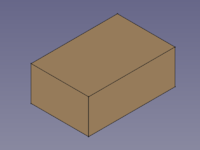
To create a hollow cuboid with the Part Workbench:
- Create a solid using either:
- Part Box.
- Part Extrude from:
- A Draft Rectangle.
- A Draft Wire.
- A Sketch.
- A
- Use Part Thickness to create a shell object from the solid (Typically with the thickness value of the sheet metal).
To create a hollow cuboid with the PartDesign Workbench:
- Create a solid using either:
- Additive Box.
- PartDesign Pad from a Sketch.
- Use
 PartDesign Thickness to create a shell object from the solid (Typically with the thickness value of the sheet metal).
Proprietà
See also: Property View.
A SheetMetal Relief object is derived from a Part Feature object or, if it is inside a PartDesign Body, from a PartDesign Feature object, and inherits all its properties. It also has the following additional properties:
Dati
Parameters
- Datibase Object (
LinkSub): "Base Object". Links to the corner vertexes defining relief positions. - Datirelief (
Length): "Relief Size". Default:2,00 mm.
Questa pagina è recuperata da https://wiki.freecad.org/SheetMetal_AddRelief