This documentation is not finished. Please help and contribute documentation.
GuiCommand model explains how commands should be documented. Browse Category:UnfinishedDocu to see more incomplete pages like this one. See Category:Command Reference for all commands.
See WikiPages to learn about editing the wiki pages, and go to Help FreeCAD to learn about other ways in which you can contribute.
|
|
| Menu location |
|---|
| SheetMetal → Add Corner Relief |
| Workbenches |
| SheetMetal |
| Default shortcut |
| C R |
| Introduced in version |
| - |
| See also |
| None |
Description
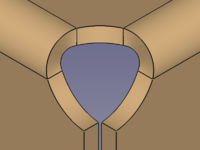
The ![]() SheetMetal AddCornerRelief command adds a corner relief. A relief is usually created at corners where two bends meet, but the command can also create a relief at an open corner.
SheetMetal AddCornerRelief command adds a corner relief. A relief is usually created at corners where two bends meet, but the command can also create a relief at an open corner.
The command can only create one relief at a time.
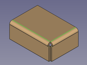
![]()
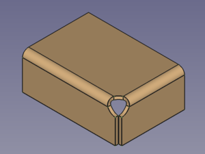
Default corner of two bends → Corner with added corner relief
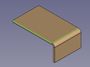
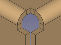
![]()
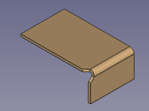
Default open corner → Open corner with added corner relief
Usage
- Select two edges of a corner.
- There are several ways to invoke the command:
- Press the
 Add Corner Relief button.
 - Select the SheetMetal → Add Corner Relief option from the menu.
- Right-click in the Tree View or the 3D View and select the Sheet Metal → Add Corner Relief option from the context menu.
- Use the keyboard shortcut: C then R.
- Press the
- A CornerRelief object is created and the Corner relief properties Task Panel opens (introduced in version 0.5.00).
- A new corner relief is added at the selected corner.
- Optionally press the Select button to reselect the edges.
- Press the Preview button to finish the selection and display the changes.
- Optionally re-select one of the Relief Type radio buttons:
- The Circular radio button creates a round relief cutout.
- The Square radio button creates a square relief cutout.
- The Sketch radio button creates a cutout based on a sketch.
- Press the Sketch button to select the sketch.
- Optionally adjust the X offset and Y offset parameters.
- Optionally toggle the Relief Size radio buttons:
- Select Absolute and enter the Relief Size in mm.
- Select Relative and enter the Scale Factor.
- Optionally adjust the K-Factor.
- Press the OK button to finish the command and close the Task Panel.
- Optionally adjust the parameters in the Property View.
Task Panel
A task panel was introduced in version 0.5.00
Double-click an existing CornerRelief object in the Tree View to re-open the task panel and edit the parameters.

- Base Select: Links selected edges to the base Object property.
- The Circular, Square and Sketch radio buttons in combination with the Absolute and Relative radio buttons set the Relief Sketch property.
- If the Sketch radio button is selected the following options are displayed:
- Sketch: Links a Sketch to the Sketch property.
- X Offset: Sets the XOffset property.
- Y Offset: Sets the YOffset property.
- If the Absolute radio button is selected:
- Relief Size: Sets the Size property.
- If the Relative radio button is selected:
- Scale Factor: Sets the Size Ratio property.
- K Factor: Sets the kfactor property.
Relief shapes
The shape of a corner relief can be altered by changing its property values:
The value of the property DataReliefSketch can be chosen from a list: Circle (default), Circle-Scaled, Square, Square-Scaled, Sketch.
CircleandSquareuse the value of the property DataSize to scale the relief.Circle-ScaledandSquare-Scaleduse the value of the property DataSize Ratio to scale the relief.Sketchactivates the use of the sketch listed in the property DataSketch to define the relief shape.
![]()
![]()
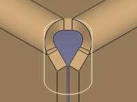
Circular relief (default settings) → Square relief (default settings) → Sketch based relief
A closer look at relief sizes
To get an idea how and where the relief is placed we unfold a default corner without a relief.
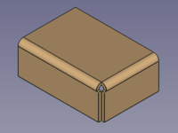
![]()
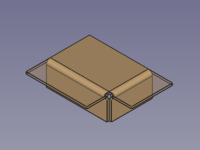
![]()
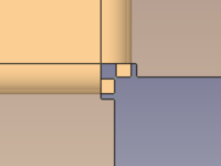
Default corner of two bends → Corner with unfold solid → Corner in top view
The next step is to open the unfold sketch, create a circle through 3 points and add a radius dimension.
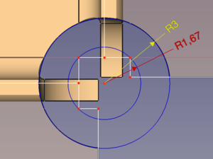
Now we add a corner relief, create the corresponding unfold solid and open the first unfold sketch again.
Adding a concentric circle of 3 mm radius reveals that we have found out how the internal circle is positioned as the new circle fits perfectly into the cut-out of the relief's unfold solid.
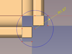
![]()
Default corner with unfold sketch → Corner with default relief and the same unfold sketch
Trying to set the property DataSize to a value below the determined 1,67 mm will result in an error; any value above should work fine.
Switching to Circle-Scaled and creating another unfold solid shows that 1,67 mm is the base for the property DataSize Ratio, too.
Notes
- The k factor defines where within the thickness of a sheet the neutral axis is located according to the ANSI standard.
- The selection accepts more than two edges, but only the first two edges are taken into account.
Properties
See also: Property View.
A SheetMetal CornerRelief object is derived from a Part Feature object or, if it is inside a PartDesign Body, from a PartDesign Feature object, and inherits all its properties. It also has the following additional properties:
Data
Parameters
- DataReliefSketch (
Enumeration): "Corner Relief Type".Circle(default),Circle-Scaled,Square,Square-Scaled,Sketch. - DataSize (
Length): "Size of Shape". Default:3,00 mm. - DataSize Ratio (
Float): "Size Ratio of Shape". Default:1,50. - Database Object (
LinkSub): "Base Object". Links to the pair of edges defining the Corner Relief position. - Datakfactor (
FloatConstraint): "Neutral Axis Position". Default:0,50.
Parameters1
- DataSketch (
Link): "Corner Relief Sketch". - DataXOffset (
Distance): "Gap from side one". Default:0,00 mm. - DataYOffset (
Distance): "Gap from side two". Default:0,00 mm.
This page is retrieved from https://wiki.freecad.org/SheetMetal_AddCornerRelief