| Тема |
|---|
| Robot Workbench |
| Уровень |
| Intermediate |
| Время для завершения |
| Unknown |
| Авторы |
| FreeCAD версия |
| Примеры файлов |
| Смотрите также |
| None |
Обзор
This article is about bringing a standard 6-Axis industry robot into FreeCAD for simulation in the ![]() Robot Workbench
Robot Workbench
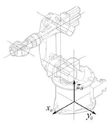
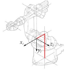
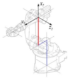
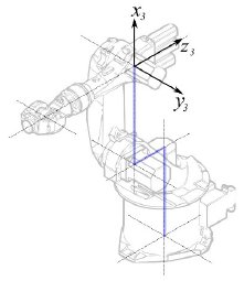
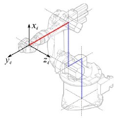
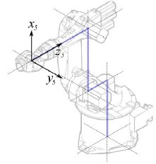
The description follows the Denavit-Hartenberg Parameter system, as also described in John J. Craigs book "Introduction to Robotics".
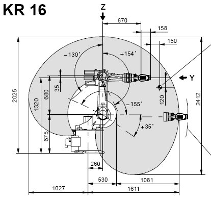
Example Kuka
|
|
|
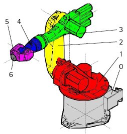
Кинематика (кинематическая модель движений)
Segment |
Parameter |
Description |
|---|---|---|
|
Base configuration | |
|
° |
Segment 1 |
|
°
° |
Segment 2 |
|
° |
Segment 3 |
|
° |
Segment 4 |
|
° |
Segment 5 |

|
° |
Segment 6 |
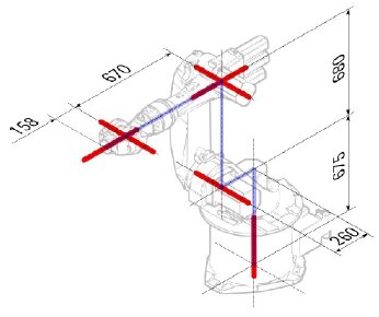
This leads to following table:
| 1 | q1 | 675 mm | 260 mm | -90° |
| 2 | q2 - 90° | 0 mm | 680 mm | 0° |
| 3 | q3 | 0 mm | 0 mm | 90° |
| 4 | q4 | -670 mm | 0 mm | -90° |
| 5 | q5 | 0 mm | 0 mm | 90° |
| 6 | q6 | -158 mm | 0 mm | 180° |
Since the Kuka robots do not have all axis to 0 in the drawn L-Position, we have to change axis 2 & 3 by 90°.
| 1 | q1 | 675 mm | 260 mm | -90° |
| 2 | q2 | 0 mm | 680 mm | 0° |
| 3 | q3 - 90° | 0 mm | 0 mm | 90° |
| 4 | q4 | -670 mm | 0 mm | -90° |
| 5 | q5 | 0 mm | 0 mm | 90° |
| 6 | q6 | -158 mm | 0 mm | 180° |
In the data sheet we find additional information about the axis:
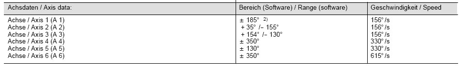
That leads to this complete table:
| Axis Speed | |||||||
|---|---|---|---|---|---|---|---|
| 1 | 0 | 675 | 260 | -90 | -185 | 185 | 156 |
| 2 | 0 | 0 | 680 | 0 | -155 | 35 | 156 |
| 3 | - 90 | 0 | 0 | 90 | -130 | 154 | 156 |
| 4 | 0 | -670 | 0 | -90 | -350 | 350 | 330 |
| 5 | 0 | 0 | 0 | 90 | -130 | 130 | 330 |
| 6 | 0 | -158 | 0 | 180 | -350 | 350 | 615 |
Visual representation
FreeCAD can generate a rough visual out of the kinematic table. But if you want closer to reality you can use a VRML file with the robot shape for the simulation. E.g. Kuka delivers for its model VRML files. The VRML file gets loaded while the creation of the specific robot in FreeCAD. In order to allow FreeCAD to move the axis we have to edit the VRML file and insert special transformation nodes FreeCAD can find and manipulate.
Again shown by the example Kuka KR 16. Beginning from line 1:
#VRML V2.0 utf8
#
# This VRML97 file was exported using eM-Workplace
# (c) Tecnomatix Technologies GmbH & Co. KG
#     Heisenberg-Bogen 1
#     D-85609 Aschheim-Dornach
#     GERMANY
#
#Background
#{
#   skyColor   [0.752941 0.752941 0.752941]
#}
Transform
{
   #rotation 1 0 0 -1.5707963
   #scale .001 .001 .001
   children
   [
           DEF AOBJ_0001_000_TRAFO Transform
           {
              children
              [
...
You see this file is exported with a robot simulation software called Tecnomatix. Remove this notice and put in a URL where you get this file from, because Tecnomatix has no copyright in the file content. It's only a converter! First of all we remove the Background node. Then remove the rotation and scale node to get the model to mm and upright Z.
Right at the end:
  ] }
  ] }
  ] }
  ]
}
#ROUTE SENS_04_OBJ.rotation_changed TO AXIS_04_OBJ.rotation
#ROUTE SENS_27_OBJ.rotation_changed TO AXIS_27_OBJ.rotation
#ROUTE SENS_32_OBJ.rotation_changed TO AXIS_32_OBJ.rotation
#ROUTE SENS_44_OBJ.rotation_changed TO AXIS_44_OBJ.rotation
#ROUTE SENS_46_OBJ.rotation_changed TO AXIS_46_OBJ.rotation
#ROUTE SENS_49_OBJ.rotation_changed TO AXIS_49_OBJ.rotation
#DEF AnySIMTimer TimeSensor
#{
#   cycleInterval 1.000000
#   loop          TRUE
#}
Comment out the TimeSensor and the 6 routes. This 6 lines give you a hint where the actual axis of the robot are! First search for "AXIS_04_OBJ" that brings you to that place:
...
    Transform { rotation 1 0 0 1.570796 children [
        DEF SENS_04_OBJ-0001 CylinderSensor
        {
           diskAngle 1.570796
           minAngle  -3.228859
           maxAngle  3.228859
           offset    0.000000
        }
      DEF FREECAD_AXIS1 Transform { rotation 0 1 0 0 children [
      DEF AXIS_04_OBJ-0001 Transform
     {
        children
        [
        Transform { rotation 1 0 0 -1.570796 children [
           DEF AOBJ_0001_003_TRAFO Transform
           {
              rotation 1.000000 0.000000 0.000000 3.141593
              translation -600.000000 500.000000 300.000000
              children
              [
...
You have to insert exactly above the definition of this node the line
"DEF FREECAD_AXIS1 Transform { rotation 0 1 0 0 children ["
which is the anchor for FreeCAD to move the axis.
Now do the same for FREECAD_AXIS2,FREECAD_AXIS3,FREECAD_AXIS4,FREECAD_AXIS5 and FREECAD_AXIS6. Don't forget the closing brackets at the end of the file and you're done!
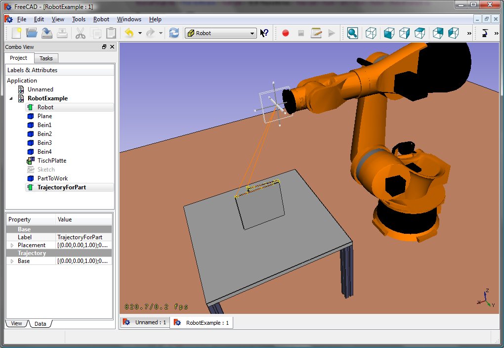
You can load the VRML by instantiating the robot:
App.activeDocument().addObject("Robot::RobotObject","Robot")
App.activeDocument().Robot.RobotVrmlFile = "C:/_Projekte/FreeCAD0.9_build/mod/Robot/Lib/Kuka/kr16.wrl"
which should give you that result:
KR 210
| Axis Speed | |||||||
|---|---|---|---|---|---|---|---|
| 1 | 0 | 750 | 350 | -90 | -185 | 185 | 156 |
| 2 | 0 | 0 | 1250 | 0 | -155 | 35 | 156 |
| 3 | - 90 | 0 | 0 | 90 | -130 | 154 | 156 |
| 4 | 0 | -1100 | 0 | -90 | -350 | 350 | 330 |
| 5 | 0 | 0 | 0 | 90 | -130 | 130 | 330 |
| 6 | 0 | -230 | 0 | 180 | -350 | 350 | 615 |
KR 500
| Axis Speed | |||||||
|---|---|---|---|---|---|---|---|
| 1 | 0 | 1045 | 500 | -90 | -185 | 185 | 156 |
| 2 | 0 | 0 | 1300 | 0 | -155 | 35 | 156 |
| 3 | - 90 | 0 | 0 | 90 | -130 | 154 | 156 |
| 4 | 0 | -1025 | 0 | -90 | -350 | 350 | 330 |
| 5 | 0 | 0 | 0 | 90 | -130 | 130 | 330 |
| 6 | 0 | -250 | 0 | 180 | -350 | 350 | 615 |
Links
- Springer Handbook of Robotics, section Kinematics, p 9-33.
- Denavit-Hartenberg Parameter 3D Video Tutorial Denavit-Hartenberg Parameter 3D Video Tutorial for a KUKA industry robot on YouTube (german).
- Denavit-Hartenberg Reference Frame Layout Denavit-Hartenberg Reference Frame Layout on YouTube.
- RoboAnalyzer RoboAnalyzer is a 3D model based software that can be used to teach and learn the Robotics concepts.
Эта страница получена от https://wiki.freecad.org/Robot_6-Axis