
Introduction
The ![]() Draft Workbench is primarily focused on the creation and modification of 2D objects in FreeCAD. But it is not restricted to the XY-plane of the global coordinate system. Its objects can have any orientation and position in 3D space, and some Draft objects can either be planar or non-planar.
Draft Workbench is primarily focused on the creation and modification of 2D objects in FreeCAD. But it is not restricted to the XY-plane of the global coordinate system. Its objects can have any orientation and position in 3D space, and some Draft objects can either be planar or non-planar.
Draft objects can be used for general drafting, similar to what can be done with Inkscape or AutoCAD. But they can also form the base for the creation of 3D objects in other workbenches. A Draft Wire may define the path of an Arch Wall, a Draft Polygon can be extruded with Part Extrude, etc. Many of the Draft modifier tools can be applied to 2D and 3D objects created with other workbenches as well. You can, for example, move a Sketch or create a Draft OrthoArray from a Part object.
The Draft Workbench also provides tools to define a working plane, a grid, and a snapping system to precisely control the position of geometry.
If your primary goal is the production of complex 2D drawings and DXF files, and you don't need 3D modelling, FreeCAD may not be the right choice for you. You may wish to consider a dedicated software program for technical drafting instead, such as LibreCAD or QCad.
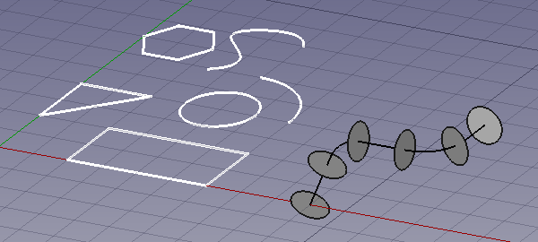
The image shows the grid aligned with the XY-plane.
On the left, in white, several planar objects.
On the right a non-planar Draft Wire used as the Path Object of a Draft PathArray.
Drafting
 Line: creates a straight line.
 Polyline: creates a polyline (also called wire), a sequence of several connected line segments.
 Fillet: creates a fillet, a rounded corner, or a chamfer, a straight edge, between two selected edges.

 Arc Tools:
- Arc: creates a circular arc from a center, a radius, a start angle and an aperture angle.
 Arc From 3 Points: creates a circular arc from three points that define its circumference.
 Circle: creates a circle from a center and a radius.
 Ellipse: creates an ellipse from two points defining a rectangle in which the ellipse will fit.
 Rectangle: creates a rectangle from two points.
 Polygon: creates a regular polygon from a center and a radius.
 B-Spline: creates a B-spline curve from several points.
 Bézier Tools:
- Cubic Bézier Curve: creates a Bézier curve of the third degree.
 Bézier Curve: creates a Bézier curve from several points.
 Point: creates a simple point.
 Facebinder: creates a surface object from selected faces.
 Shape From Text: creates a compound shape that represents a text string.
 Hatch: creates hatches on the planar faces of a selected object.
Annotation
 Text: creates a multi-line text at a given point.
 Dimension: creates a linear dimension, a radial dimension or an angular dimension.
 Label: creates a multi-line text with a 2-segment leader line and an arrow.
 Annotation Styles: allows you to define styles that affect the visual properties of annotation-like objects.
Modification
 Move: moves or copies selected objects from one point to another.
 Rotate: rotates or copies selected objects around a center point by a given angle.
 Scale: scales or copies selected objects around a base point.
 Mirror: creates mirrored copies from selected objects.
 Offset: offsets each segment of a selected object over a given distance, or creates an offset copy of the selected object.
 Trimex: trims or extends a selected object.
 Stretch: stretches objects by moving selected points.
 Clone: creates linked copies, clones, of selected objects.
 Array Tools:
 Polar Array: creates an array from a selected object by placing copies along a circle. It can optionally create a Link array.
 Circular Array: creates an array from a selected object by placing copies along concentric circles. It can optionally create a Link array.
 Path Array: creates an array from a selected object by placing copies along a path.
 Path Link Array: idem, but create a Link array instead of a regular array.
 Point Array: creates an array from a selected object by placing copies at the points from a point compound.
 Point Link Array: idem, but create a Link array instead of a regular array.
 Edit: puts selected objects in Draft Edit mode. In this mode the properties of objects can be edited graphically.
 Highlight Subelements: temporarily highlights selected objects, or the base objects of selected objects.
 Join: joins Draft Lines and Draft Wires into a single wire.
 Split: splits a Draft Line or Draft Wire at a specified point or edge.
 Upgrade: upgrades selected objects.
 Downgrade: downgrades selected objects.
 Convert Wire/B-Spline: converts Draft Wires to Draft B-splines and vice versa.
 Draft to Sketch: converts Draft objects to Sketcher Sketches and vice versa.
 Set Slope: slopes selected Draft Lines or Draft Wires by increasing, or decreasing, the Z coordinate of all points after the first one.
 Flip Dimension: rotates the dimension text of selected Draft Dimensions 180° around the dimension line.
 Shape 2D View: creates 2D projections from selected objects.
Draft Tray
The Draft Tray allows selecting the working plane, defining style settings, toggling construction mode, and specifying the active layer or group.
![]()
 Working Plane: defines the current Draft working plane. Also available in the menu: Draft → Utilities →
  Working Plane.
 Set Style: sets the default style for new objects. Also available in the menu: Draft → Utilities →
  Set Style.
 Toggle Construction Mode: switches Draft construction mode on or off. Also available in the menu: Draft → Utilities →
  Toggle Construction Mode.
 AutoGroup: changes the active Draft Layer or, optionally, the active Std Group or group-like BIM object.
Draft Scale Widget
With the Draft Scale Widget the Draft annotation scale can be specified.
![]()
Draft Snap Widget
The Draft Snap Widget can be used as an alternative for the Draft Snap toolbar.
![]()
Draft Snap toolbar
With the Draft Snap toolbar the active snap options can be selected. The buttons belonging to active options stay depressed. For general information about snapping see: Draft Snap.
 Snap Lock: enables or disables snapping globally.
 Snap Endpoint: snaps to the endpoints of edges.
 Snap Midpoint: snaps to the midpoint of edges.
 Snap Center: snaps to the center point of faces and circular edges, and to the ДаніPlacement point of Draft WorkingPlaneProxies and Arch BuildingParts.
 Snap Angle: snaps to the special cardinal points on circular edges, at multiples of 30° and 45°.
 Snap Intersection: snaps to the intersection of two edges, and (introduced in 1.1) the intersection of a face and an edge.
 Snap Perpendicular: snaps to the perpendicular points on faces (introduced in 0.21) and edges.
 Snap Extension: snaps to an imaginary line that extends beyond the endpoints of straight edges.
 Snap Parallel: snaps to an imaginary line parallel to straight edges.
 Snap Special: snaps to special points defined by the object.
 Snap Near: snaps to the nearest point on faces and edges.
 Snap Ortho: snaps to imaginary lines that cross the previous point at multiples of 45°.
 Snap Grid: snaps to the intersections of grid lines.
 Snap Working Plane: projects snap points onto the current working plane.
 Snap Dimensions: shows temporary X and Y dimensions.
 Toggle Grid: changes the visibility of the grid.
Draft Utilities toolbar
 Manage Layers: allows to manage the layers in a document. introduced in 0.21
 New Named Group: creates a named Std Group and adds objects to that group.
 Select Group: selects the contents of Std Groups or group-like BIM objects.
 Add to Layer: adds objects to a layer, or removes them from any layer. introduced in 1.1
 Add to Group: adds objects to a Std Group. It can also ungroup objects.
 Add to Construction Group: adds objects to the Draft construction group.
 Toggle Wireframe: switches the ВиглядDisplay Mode property of selected objects between
 Flat LinesandWireframe.
 Working Plane Proxy: creates a working plane proxy to save the current Draft working plane.
Additional tools
The Draft → Utilities menu contains several tools. Most of them can also be accessed from toolbars or the Draft Tray and have already been mentioned above. For the following tools this is not the case:
 Apply Current Style: applies the current style settings to selected objects.
 New Layer: creates a Draft Layer.
 Heal: heals problematic Draft objects found in very old files.
 Show Snap Toolbar: shows the Draft Snap toolbar.
Additional features
- Working plane: the plane in the 3D View where new Draft objects are created.
- Snapping: select exact geometric points on, or defined by, existing objects or the grid.
- Constraining: for each subsequent point you can constrain the movement of the cursor to the X, Y, or Z direction.
- Construction mode: places new Draft objects in a dedicated group making it easier to hide or delete them.
- Pattern: Draft objects with a ДаніMake Face property can display an SVG pattern instead of a solid face color.
The following additional options are available in the Tree View context menu:
Default options
For most Draft objects the following option is available:
- Edit: edits the object. Depending on the object type either Draft Edit or a dedicated edit solution is used. introduced in 0.21
If there is an active document the context menu contains an additional sub-menu:
- Utilities: a subset of the tools available in the main Draft Utilities menu.
Layer container options
For a Draft LayerContainer these additional options are available:
 Add New Layer: adds a new layer to the current document.
- Reassign Properties of All Layers: removes overrides from objects in all layers. introduced in 1.1
 Merge Layer Duplicates: merges all layers with the same base label.
Layer options
For a Draft Layer these additional options are available:
 Activate Layer: activates the selected layer.
- Reassign Properties of Layer: removes overrides from objects in the layer. introduced in 1.1
- Select Layer Contents: selects the objects inside the selected layer.
Text options
For a Draft Text and a Draft Label that contains one or more hyperlinks, to a local or remote file or an URL, this additional option is available:
- Open Links: the hyperlinks are opened in the appropriate application (as defined by the OS). There is a warning in the case of multiple hyperlinks. introduced in 1.0
Wire options
For a Draft Line and a Draft Wire this additional option is available:
- Flatten: flattens the wire on the current Draft working plane.
Working plane proxy options
For a Draft WorkingPlaneProxy these additional options are available:
- Save Camera Position: updates the ВиглядView Data property of the working plane proxy with the current 3D View camera settings.
- Save Visibility of Objects: updates the ВиглядVisibility Map property of the working plane proxy with the current visibility state of objects in the document.
The following additional options are available in the 3D View context menu:
Default options
If there is an active document the context menu contains one additional sub-menu:
- Utilities: a subset of the tools available in the main Draft Utilities menu.
Text options
See above.
Obsolete tools
 Array: creates an orthogonal array from a selected object. The created array can be turned into a polar array or a circular array by changing its ДаніArray Type property. Not available in 0.21 and above.
 Toggle continue mode: switches continue mode on or off. Not available in 1.0 and above.
Preferences
 Preferences: general preferences for the Draft Workbench.
 Import Export Preferences: preferences available for importing from and exporting to different file formats.
File formats
The Draft Workbench provides FreeCAD with importers and exporters for several file formats. These are used by the Std Import and Std Export commands.
- Autodesk .DXF: imports and exports Drawing Exchange Format files. See also FreeCAD and DXF Import.
- Autodesk .DWG: imports and exports DWG files via an external DWG converter. See also FreeCAD and DWG Import.
- Scalable Vector Graphics .SVG: imports and exports Scalable Vector Graphics files.
- Open Cad Format .OCA: imports and exports OCA/GCAD files.
- Airfoil Data Format .DAT: imports DAT files describing Airfoil profiles.
Unit tests
See also: Test Workbench.
To run the unit tests of the workbench execute the following from the operating system terminal:
freecad -t TestDraft
Scripting
See also: Autogenerated API documentation and FreeCAD Scripting Basics.
The workbench includes a module to create samples of all objects in a new document.
Use this to test that all objects are produced correctly:
import drafttests.draft_test_objects as dto
doc = dto.create_test_file()
Inspecting the code of this module can help to understand the programming interface.
Tutorials
Цю сторінку отримано з https://wiki.freecad.org/Draft_Workbench