|
|
| Menyplacering |
|---|
| Arch → Structure |
| Arbetsbänkar |
| Arch |
| Standard genväg |
| S T |
| Introducerad i version |
| - |
| Se även |
| Arch Wall Arch Rebar/sv |
Beskrivning
The Arch Structure tool allows you to build structural elements such as columns or beams, by specifying their width, length and height, or by basing them on a 2D profile (face, wire or sketch).
If no profile is given, a set of presets are available to quickly build a structural element from a predefined standard profile.

Column based on a 2D base profile; a column and a beam defined by their height, length and width, without a base profile; a metallic structure based on a 2D face
Bruk
- Select a 2D shape (Draft object, face or sketch) (optional).
- Select the Utils → Structure Tools →
 Structure option from the menu.
 - Adjust the desired properties.
Options
- When no base 2D object is selected, the structure tool has 2 drawing modes: Column and beam:
- In column mode, you are asked to pick one point on screen or by entering coordinates. The new structural object will be placed at that point.
- In beam mode, you are asked to pick two points on screen or by entering coordinates. The new structural object will span between these two points.
- The height, width and length of a structure can be adjusted after creation
- Press Esc or the Cancel button to abort the current command.
- Double-clicking on the structure in the Tree View after it is created allows you to enter edit mode and access and modify its additions and subtractions
- In edit mode, it is also possible to add axes systems to the structural element. When adding one axes system, the structural element will be copied once on each axis of the system. When adding two axes systems, the structural element will be copied once on each intersection of the two systems.
Properties
An Arch Structure object shares the common properties and behaviors of all Arch Components.
Data
Component
See Arch Component.
Extrusion Path
- DataBase Mirror (
Bool): TBD - DataBase Offset X (
Distance): TBD - DataBase Offset Y (
Distance): TBD - DataBase Perpendiculat To Tool (
Bool): TBD - DataRotation (
Angle): TBD - DataComputed Length (
Length): TBD - DataTool (
LinkSubList): an optional extrusion path, which can be any type of wire. If this property is empty, the extrusion will be straight, and happen in the direction given by the DataNormal property - DataTool Offset First (
Distance): TBD - DataTool Offset Last (
Distance): TBD
IFC
See Arch Component.
IFC Attributes
See Arch Component.
Structure
- DataFace Maker (
Enum): specifies the type of face generation algorithm to use to build the profile. The options are:NoneSimple: makes faces from all closed wires, ignoring overlaps.Cheese: makes faces with holes, but no faces within holes.Bullseye: makes faces with holes, including islands within holes.
- DataHeight (
Length): specifies the height of the structure, or the extrusion length when based on a profile. If no height is given, and the structure is inside an Arch Floor object with its height defined, the structure will automatically take the value of the floor height. - DataLength (
Length): specifies the length of the structure. This is only used if the structure is not based on a profile. - DataNodes (
VectorList): TBD. - DataNodes Offset (
Distance): specifies an optional offset between the centerline and the nodes line. - DataNormal (
Vector): specifies the direction in which the base face of this structure will be extruded. If this property is kept to (0,0,0), the direction will be automatically set to the normal direction of the base face. - DataProfile (
String): TBD. - DataWidth (
Length): specifies the width of the structure. This is only used if the structure is not based on a profile.
View
- VyNodes Type: The type of structural nodes of this object, linear or area.
- VyShow Nodes: Shows or hides the structural nodes.
Presets
The Structure tool also features a series of presets that allow to quickly build standard metallic profiles or precast concrete elements.
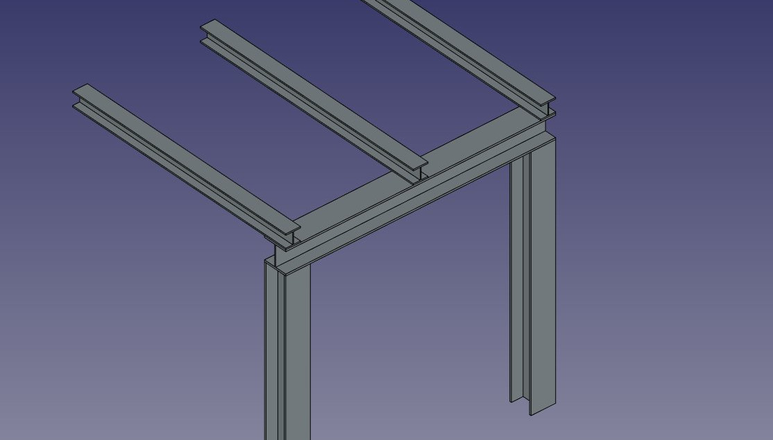
Some presets for steel structures
The presets are obtained by choosing a Category from the structure options panel. Available categories are Precast concrete or any of the industry-standard metallic profiles such as HEA, HEB or INP. For each of these categories, a number of presets are available. Once a preset is chosen, its individual parameters such as Length, Width or Height can be adjusted. However, for metallic profiles, the profile size is set by the preset and cannot be changed.
- The Switch Length/Height button can be used to switch Length and Height values, and therefore building a horizontal beam rather than a vertical column.
- The Switch Length/Width button can be used to switch Length and Width values.
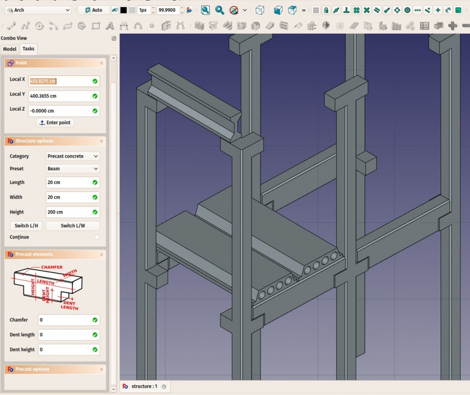
Some presets for precast concrete structures
Structural nodes
Structural objects also have the ability to display structural nodes. Structural nodes are a sequence of 3D points stored in a DataNodes (VectorList) property. By switching the VyShow Nodes view property on/off, one can see the structural nodes of a structural element:
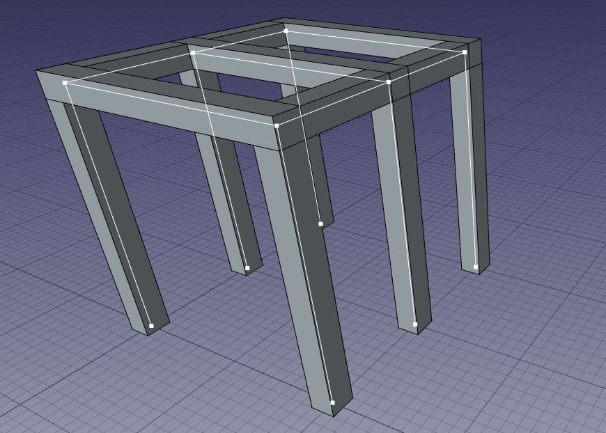
Structural nodes made visible for a set of structures
- Nodes are calculated and updated automatically, as long as you don't modify them manually. If you did, they won't be updated if the shape of the structural object changes, unless you use the "Reset nodes" tool below.
- Arch structures can have not only linear nodes, but also planar nodes. For this:
- There must be at least 3 vectors in the "Nodes" property of the object.
- The VyNodes Type property of their ViewObject must be set to "Area".
- When the nodes calculation is automatic (that is, if you never touched them manually), when setting the "Role" property of a structure to "Slab", it will automatically become a planar node (there will be more than 3 vectors and the VyNodes Type property will be set to "Area").
- When editing a structure object (double-click), a couple of node tools are available in the task panel:
- Reset the nodes to automatic calculation, in case you modified them manually
- Edit the nodes graphically, works the same way as Draft Edit
- Extend the nodes of the edited object until it touches the node of another object
- Make the node of this object and another one coincident
- Toggle the display of all nodes of all structural objects of the document on/off
Scripting
Skript
The Structure tool can be used in macros and from the Python console by using the following function:
structure = makeStructure(baseobj=None, height=None)
structure = makeStructure(baseobj=None, length=None, width=None, height=None, name="Structure")
- Creates a
structureobject from the givenbaseobj, which is a closed profile, and the given extrusionheight.- If no
baseobjis given, you can provide the numerical values for thelength,width, andheightto create a block structure. - The
baseobjcan also be any existing solid object.
- If no
Example:
import FreeCAD
import Draft
import Arch

rect = Draft.make_rectangle(200, 300)
structure1 = Arch.makeStructure(rect, height=2000)
FreeCAD.ActiveDocument.recompute()

structure2 = Arch.makeStructure(None, length=500, width=1000, height=3000)
Draft.move(structure2, FreeCAD.Vector(2000, 0, 0))
FreeCAD.ActiveDocument.recompute()
Denna sida hämtas från https://wiki.freecad.org/Arch_Structure