|
|
| Menu location |
|---|
| TechDraw → TechDraw Views → Section View |
| Workbenches |
| TechDraw |
| Default shortcut |
| None |
| Introduced in version |
| - |
| See also |
| TechDraw ComplexSection, TechDraw View |
Descripción
The TechDraw SectionView tool inserts a cross-section view based on an existing Part View.
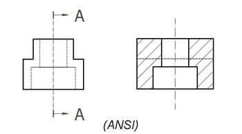
Sectioning an already placed view, which shows the internal holes and a hatched cut surface.
The top image shows the ANSI arrow format.
The bottom image shows the ISO arrow format.
Utilización
- Select a Part View in the 3D View or Tree View.
- There are several ways to invoke the tool:
- Press the
 Section View button.
 - Select the TechDraw → TechDraw Views → Section View option from the menu.
- Press the
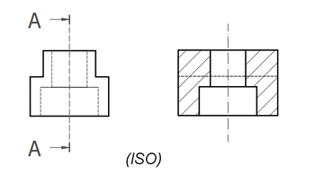
- A task panel opens which will help calculate the various properties. Reasonable values for the view Direction are calculated, but these can be changed.
Task panel to define the sectional cut of a view
Properties
See also: Property View.
In the properties of the DatosBase View you can change the appearance of the section line.
A Section View, formally a TechDraw::DrawViewSection object, is derived from a Part View, formally a TechDraw::DrawViewPart object, and inherits all its properties. It also has the following additional properties:
Datos
Appearance
- DatosSection Line Stretch (
FloatConstraint): Adjusts the length of the section line.1.0is normal length,1.1would be 10% longer,0.9would be 10% shorter. introduced in 1.0
Cut Operation
- DatosFuse Before Cut (
Bool): Fuse the source shapes before performing the section cut. - DatosTrim After Cut (
Bool): Additionally trim the resulting shape after the section cut to remove any unwanted pieces. introduced in 0.21 - DatosUse Previous Cut (
Bool) Use the cut shape from the base view instead of the original object. introduced in 1.0
Cut Surface Format
- DatosCut Surface Display (
Enumeration): Appearance of the cut surface. Options:Hide: Hides the cut surface, only the outline will be displayed.Color: Colors the cut surface using the setting of Cut Surface Color in the TechDraw preferences.SvgHatch: Hatches the section cut using a hatchPatHatch: Hatches the section cut using a geometric hatch
- DatosFile Hatch Pattern (
File): Full path to SVG hatch pattern file. - DatosFile Geom Pattern (
File): Full path to PAT pattern file. - DatosSvg Included (
FileIncluded): Full path to the included SVG hatch pattern file. - DatosPat Included (
FileIncluded): Full path to the included PAT pattern file. - DatosName Geom Pattern (
String): Name of the PAT pattern to use. - DatosHatch Scale (
Float): Hatch pattern size adjustment. - DatosHatch Rotation (
Float): Rotation of hatch pattern in degrees counter-clockwise. introduced in 0.21 - Datos (Hidden)Hatch Offset (
Vector): Hatch pattern offset. introduced in 0.21
Section
- DatosSection Symbol (
String): The identifier for this section. - DatosBase View (
Link): The view on which this section is based. - DatosSection Normal (
Vector): A vector describing the direction normal to the cutting plane. - DatosSection Origin (
Vector): A vector describing a point on the cutting plane. Typically the centroid of the original part. - DatosSection Direction (
Enumeration): The direction in the Base View for this section. Options:Aligned,Right,Left,UporDown.
Vistas
Cut Surface
- VistaCut Surface Color (
Color): Solid color for surface highlight. Used if DatosCut Surface Display is set toColor. - Vista (Hidden)Show Cut Surface (
Bool): Show/hide the cut surface.
Surface Hatch
- VistaGeom Hatch Color (
Color): The color of the Geometric hath pattern. - VistaHatch Color (
Color): The color of the Svg hatch pattern. - Vista (Hidden)Hatch Cut Surface (
Bool): Hatch the cut surface. - VistaWeight Pattern (
Float): Line weight of the Geometric hatch pattern.
Notas
- Section Line Format: two section line formats are supported (as depicted above) and controlled by the Preference setting "Section Line Standard" on the Annotation tab. The
ANSIoption uses "pulling arrows" (known as the "traditional format" in some areas) and theISOoption uses "pushing arrows" (also known as the "reference arrow format"). - Fuse Before Cut: the section operation sometimes fails to cut the source shapes. If Fuse Before Cut is true, the source shapes are merged into a single shape before the section operation is attempted. If you encounter problems with the section operation, try flipping this value.
- Trim After Cut: the section cut operation sometimes leaves behind a portion of the source shape. If Trim After Cut is true, an additional cut operation is performed on the result of the first cut which should remove any unwanted pieces.
- Cut Surface Display: the cut surface can be hidden, painted in a solid color, hatched using an Svg pattern (default) or hatched using a PAT pattern. See Hatching.
Scripting
See also: Autogenerated API documentation and FreeCAD Scripting Basics.
A SectionView can be created with macros and from the Python Console by using the following functions:
doc = FreeCAD.ActiveDocument
box = doc.Box
page = doc.Page

view = doc.addObject("TechDraw::DrawViewPart", "View")
page.addView(view)
view.Source = box
view.Direction = (0, 0, 1)

section = doc.addObject("TechDraw::DrawViewSection", "Section")
page.addView(section)
section.Source = box
section.BaseView = view
section.Direction = (0, 1, 0)
section.SectionNormal = (-1, 0, 0)

doc.recompute()
Examples
For some more information about section views and some use cases, have a look at: TechDraw section examples.
![]()


Esta página ha sido recuperada de https://wiki.freecad.org/TechDraw_SectionView