| Тема |
|---|
| Скетчер |
| Уровень |
| Начинающий |
| Время для завершения |
| Авторы |
| Ulrich |
| FreeCAD версия |
| Примеры файлов |
| Смотрите также |
| None |
Введение
Скетчер - это инструмент для создания 2D-объектов с целью их использования при проектировании деталей. Скетчер отличается от традиционных инструментов рисования. Чтобы показать разницу, можно построить треугольник. Треугольник полностью определяется тремя величинами, которые могут быть любыми из следующего списка: длина стороны, угол, высота, площадь. Единственное исключение - три угла, которые не определяют размер.
Чтобы построить треугольник из 3 отрезков традиционным способом, нужно сделать следующее:
- провести базовую линию
- построить две окружности с радиусом, заданным длинами двух других сторон, или вычислить координаты третьей вершины
- провести недостающие две стороны от конечных точек базовой линии до точки пересечения двух окружностей или вычисленной вершины.

На странице wikipedia:Triangle (англ.) Треугольник (рус.) приведена коллекция формул для вычисления недостающей информации для построения треугольника по минимальным исходным данным. Они необходимы, если треугольник должен быть задан по заранее вычисленным координатам.
В Скетчере всё по-другому. Формулы и приведённые выше вспомогательные построения не нужны. Чтобы понять разницу, лучше всего самостоятельно построить треугольник.
Первый эскиз: треугольник
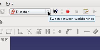
Для создания эскиза необходим открытый документ. Если открытого документа нет, новый будет создан, если щёлкнуть по ![]() . При этом должен быть выбран рабочий стол скетчера:
. При этом должен быть выбран рабочий стол скетчера:
Новый эскиз будет создан, если щёлкнуть по ![]() . Появится диалог, в котором можно выбрать ориентацию нового эскиза в 3D-пространстве. В данном случае это не имеет значения, поэтому можно подтвердить плоскость XY. Будет создан новый пустой эскиз, который откроется в режиме редактирования. Появится сетка с системой координат и красной точкой в начале координат.
. Появится диалог, в котором можно выбрать ориентацию нового эскиза в 3D-пространстве. В данном случае это не имеет значения, поэтому можно подтвердить плоскость XY. Будет создан новый пустой эскиз, который откроется в режиме редактирования. Появится сетка с системой координат и красной точкой в начале координат.
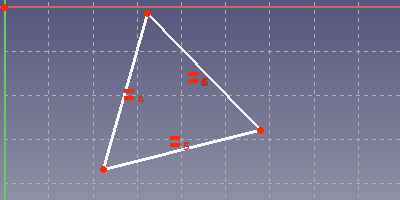
В Скетчере можно нарисовать произвольный треугольник с помощью инструмента ![]() полилинии и определить его свойства на следующем этапе. Каждый щелчок на поверхности рисунка задаёт вершину. Треугольник должен быть замкнут. Поэтому для последней линии нужно щёлкнуть по первой созданной вершине. Перед тем как щёлкнуть, рядом с указателем мыши должна появиться красная точка.
полилинии и определить его свойства на следующем этапе. Каждый щелчок на поверхности рисунка задаёт вершину. Треугольник должен быть замкнут. Поэтому для последней линии нужно щёлкнуть по первой созданной вершине. Перед тем как щёлкнуть, рядом с указателем мыши должна появиться красная точка.
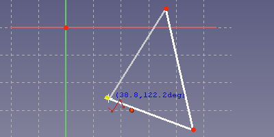
Это позволит убедиться, что последняя вершина совпадает с первой и профиль замкнут. Символы, которые появляются под курсором, обозначают автоограничения. Они устанавливаются автоматически, если щёлкнуть в этом месте. Красная точка под курсором указывает на совпадение ограничений между двумя вершинами, то есть вершины разных элементов чертежа ограничены одинаковым местоположением.
Созданный треугольник является подвижным. К вершине можно подвести мышь и перетащить её. Стороны треугольника следуют за вершиной. То же самое можно сделать с отрезком.
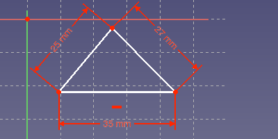
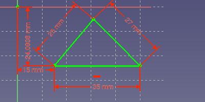
Длину каждой стороны теперь легко определить, выделив её мышью: выделенный элемент становится зелёным. Если щёлкнуть по инструменту ![]() длины, откроется диалог, в котором можно задать нужную длину. На рисунке ниже показан треугольник с длинами сторон 35 мм, 27 мм и 25 мм. Базовая линия была установлена горизонтально, для этого нужно выделить её и щёлкнуть по инструменту горизонтального ограничения
длины, откроется диалог, в котором можно задать нужную длину. На рисунке ниже показан треугольник с длинами сторон 35 мм, 27 мм и 25 мм. Базовая линия была установлена горизонтально, для этого нужно выделить её и щёлкнуть по инструменту горизонтального ограничения ![]() .
.
Эти определения длины называются ограничениями. Ограничения используются для определения фиксированной конструкции из изменяемых геометрических данных. Скетчер предоставляет все ограничения, необходимые для определения любого вида треугольника. Только площадь не может быть использована для определения треугольника. Поэтому созданный треугольник можно переопределить, изменив значение ограничения или удалив ограничения и добавив другие. Далее идёт список треугольников с другими заданными свойствами. Превратить только что созданный треугольник в один из них не составит труда.
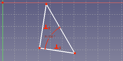
- Даны один или два угла: Необходимо выбрать две стороны треугольника. Если щёлкнуть по
 , откроется диалог для указания угла.

- Прямоугольный треугольник: Необходимо выбрать две стороны треугольника. Достаточно щёлкнуть по
 , чтобы установить прямой угол между двумя сторонами.
- Равносторонний: Одна сторона должна быть задана определенной длины. Затем нужно выбрать все стороны. Если щёлкнуть по
 , определяются два ограничения с равной длиной, чтобы придать всем сторонам одинаковую длину.
- Равносторонний треугольник (два одинаковых по длине ребра) с заданной высотой: Выберите сначала две стороны с одинаковой длиной. Щёлкните по , чтобы установить равенство между двумя сторонами. Затем выберите базовую линию и верхнюю вершину и щёлкните по инструменту длины
 .
.
Ограничения можно выбрать, щёлкнув по их символу или щёлкнув в списке ограничений. Их можно удалить, а в случае ограничений со значением - отредактировать двойным щёлчком. Данный треугольник может быть впоследствии преобразован в треугольник другого типа путём редактирования или изменения ограничений. Скетчер является частью параметрического подхода к моделированию в FreeCAD. То, что вы создали, может быть легко изменено впоследствии, если, например, потребуется другой вариант конструкции.
На показанных выше треугольниках есть белые линии. Это признак того, что у эскиза осталось несколько степеней свободы. Это можно проверить, перетащив некоторые линии или точки. Если линия или точка перемещается, значит, этот элемент не полностью определён. Эскиз, у которого нет степеней свободы, становится зелёным.
У изоскелетного треугольника отсутствует настройка длины базовой линии, и он может свободно перемещаться и вращаться в плоскости чертежа скетчера.
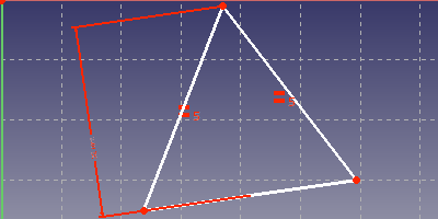
Если свойства треугольника определены, его всё равно нужно закрепить в плоскости рисования. В плоскости рисования скетчера есть система координат. Начало системы координат видно как красная точка в центре розовой оси x и светло-зелёной оси y. Самый простой способ исправить это - выбрать вершину и щёлкнуть по ![]() . Это добавит горизонтальное и вертикальное расстояние от вершины до начала системы координат. У треугольника по-прежнему может быть одна степень свободы для вращения. Поэтому одна из сторон нуждается в горизонтальном или вертикальном ограничении или в определенном угле к одной из осей системы координат. На следующем рисунке показан полностью ограниченный эскиз. Все линии и вершины теперь имеют зелёный цвет.
. Это добавит горизонтальное и вертикальное расстояние от вершины до начала системы координат. У треугольника по-прежнему может быть одна степень свободы для вращения. Поэтому одна из сторон нуждается в горизонтальном или вертикальном ограничении или в определенном угле к одной из осей системы координат. На следующем рисунке показан полностью ограниченный эскиз. Все линии и вершины теперь имеют зелёный цвет.
Подробнее об Ограничениях
Скетчер не знает формул треугольников из Википедии. Вместо этого он составляет систему уравнений для двумерных координат на основе заданных ограничений. Затем эта система уравнений решается численно.
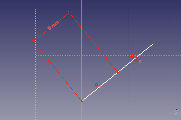
Таким образом можно решать самые разные геометрические задачи. Но есть и недостаток. Если набор уравнений имеет несколько решений, мы можем получить совсем не то, что ожидали. Это особенно неприятно, если одна и та же конструкция должна быть использована с разными размерами. Типичным симптомом является то, что после изменения ограничения длины эскиз переходит в совершенно другое состояние. Простой пример - разделение расстояния на три равные части. На следующем рисунке показаны три линии в ряд с установленными ограничениями равенства и параллельности. Общее расстояние задано равным 10 мм.
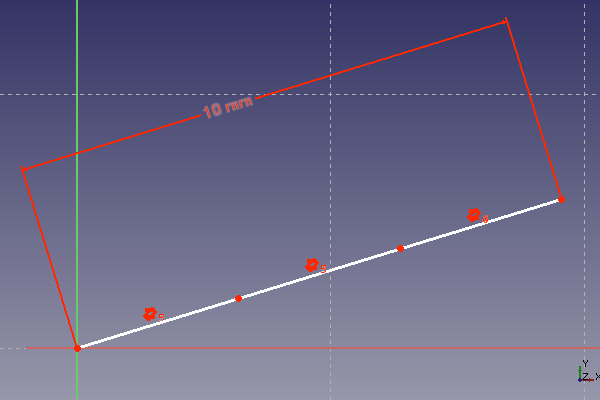
Это работает хорошо, если вводить только большие расстояния. При уменьшении расстояния свыше определенного соотношения линии складываются. Таким образом, мы получаем уже не треть от заданного расстояния, а само расстояние или две трети от него. Некоторые линии нашего ряда изменили свою ориентацию. Это по-прежнему даёт правильное решение для набора ограничений, но не то, что было задумано. На следующем изображении того же эскиза показано следующее. Ограничение по длине было установлено на 1000 мм, а затем уменьшено до 5 мм.
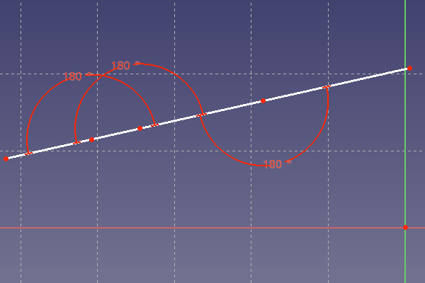
Решением является определение угла 180° между линиями раздела вместо ограничения на параллельность. Ограничение 180° имеет только одно решение. Теперь эскиз устойчив к большим изменениям расстояния. Следует отметить, что для той же цели, где это уместно, служит и ограничение 0°.
Ограничение 180° - это решение многих проблем. В некоторых старых версиях FreeCAD есть проблемы с отображением 180°-ограничения в плоскости скетчера. В большинстве случаев 180°-дуга отображается в плоскости чертежа не так, как ожидалось. Это известная проблема для FreeCAD до версии 14.3613.
В случае, когда несколько размеров увеличиваются по прямой, целесообразно сначала нарисовать зигзагообразную линию, а затем задать ограничения 180°. Это поможет не забыть про какой-то один или задать его дважды.
В следующей таблице приведены некоторые комбинации ограничений для определения простого угла. Комбинация была протестирована путём увеличения горизонтального размера длины 10 мм до больших значений, пока угольник не изменит свою ориентацию. В таблице для каждого показанного сочетания ограничений указана измененная длина, при которой происходит изменение ориентации.
| Комбинация Ограничений | Комментарии |
|---|---|
|
|
Определение длины: Ограничение равенства для определения длины |
|
|
Определение длины: Ограничение равенства для определения вертикальной длины, дуга для определения горизонтальной длины. |
|
|
Определение длины: Ограничение равенства для определения длины |
|
|
Определение длины: горизонтальная длина определяется с помощью общего ограничения длины. Ограничение равенства для определения вертикальной длины. |
|
|
Определение длины: Ограничение равенства для определения длины |
Тест показал следующее: большие изменения размерных ограничений могут привести к переворачиванию некоторых линий эскиза из-за множественного решения основной системы уравнений. Единственными ограничениями, которые сохраняют ориентацию элементов, к которым они применяются, являются ограничение угла и ограничения горизонтальных и вертикальных размеров. Различия между другими ограничениями в вопросе сохранения ориентации незначительны.
Рекомендация: Используйте угловые ограничения и ограничения горизонтальных и вертикальных размеров в критических местах, чтобы сделать эскиз устойчивым к изменениям размеров.
Проблема сочетания ограничений
Иногда два или более ограничений определяют одно и то же свойство. В качестве примера можно привести две соединённые линии, где точка соединения является центральной точкой ограничения симметрии для конечных точек линий. Теперь эти линии имеют равную длину и параллельны. Всё это является следствием ограничения симметрии.
Что произойдёт, если у этих двух линий уже есть ограничение равенства и ограничение параллельности, а также дополнительно добавлено ограничение симметрии? Теперь свойство параллельности определяется двумя ограничениями, а равенство длин также определяется двумя ограничениями. В принципе, лежащая в основе система уравнений должна иметь решение. Но могут возникнуть вычислительные проблемы. Это можно проверить, попробовав переместить линии. В большинстве случаев линии застывают, даже если скетчер по-прежнему сообщает о нескольких степенях свободы.
Описанный выше случай показывает проблему, которая кажется трудноразрешимой для разработчиков скетчера. Поэтому пользователь должен позаботиться о том, чтобы избежать подобных ситуаций. Эскизы с избыточными ограничениями действительно ведут себя неожиданно и проблематично. Симптомами избыточных ограничений являются вышеупомянутое замороженное состояние или сообщение об избыточных ограничениях после изменения другого объекта в эскизе.
Как правило, при обнаружении избыточных ограничений скетчер выдаёт предупреждение. Но этот механизм обнаружения, по-видимому, работает не во всех случаях. Когда проблема распознана, её можно избежать, просто удалив лишние ограничения. Иногда необходимо выбрать другую комбинацию ограничений.
Следующие случаи являются источниками избыточных ограничений:
- Ограничение равенства для двух радиусов одной дуги
- Ограничение симметрии для двух радиусов одной дуги
- Ограничение симметрии в сочетании с ограничениями параллельности, равенства или перпендикулярности.
Другим проблемным случаем являются параллели с точкой пересечения в бесконечности. Можно задать ограничение 180° для двух параллельных прямых без точки пересечения. Это не рекомендуется. Вместо этого следует использовать угол к другой прямой или оси.
Другая проблема - изменение ориентации углов. Это может произойти при изменении угла более чем на 180°. Если делать это небольшими шагами, то можно избежать этой проблемы.
Вспомогательные линии - Пошаговый пример
В первой части было показано, что вспомогательная геометрия не нужна для построения треугольников. Но, тем не менее, скетчер предоставляет вспомогательную геометрию, которая полезна для решения более сложных задач. Любая линия может быть преобразована в конструкционную (вспомогательную) с помощью кнопки ![]() . Линии построения (вспомогательные линии) отображаются на эскизе в виде синих линий. Они могут использоваться для ограничений так же, как и другие линии, но не отображаются и не используются, когда эскиз закрыт.
. Линии построения (вспомогательные линии) отображаются на эскизе в виде синих линий. Они могут использоваться для ограничений так же, как и другие линии, но не отображаются и не используются, когда эскиз закрыт.
Дано задание составить прямоугольник, длина стороны которого имеет золотое сечение. В Википедии показано, как построить две линии, длины которых равны золотому сечению.

Скетчер - идеальный инструмент для построения прямоугольника с золотым сечением по длине сторон. Впоследствии размер прямоугольника можно изменить, не прибегая к новому построению. Шаги построения золотого сечения, согласно Википедии, следующие:
- Имея отрезок AB, постройте перпендикуляр BC в точке B, причем BC вдвое короче AB. Начертите гипотенузу AC.
- Начертите дугу с центром C и радиусом BC. Эта дуга пересекает гипотенузу AC в точке D.
- Начертите дугу с центром A и радиусом AD. Эта дуга пересекает исходный отрезок AB в точке S. Точка S делит исходный отрезок AB на отрезки AS и SB с длинами согласно золотому сечению.
Ниже приводится пошаговое объяснение того, как это можно сделать.
- Создайте новый эскиз, как показано в примере с треугольником.
- Нарисуйте прямоугольник в эскизе. Используйте кнопку
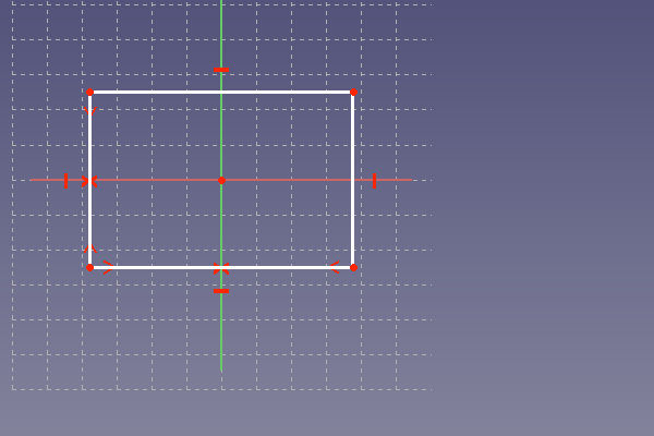
 . На следующем рисунке показан прямоугольник. FreeCAD добавил к прямоугольнику горизонтальные и вертикальные ограничения. Этот прямоугольник не может вращаться.
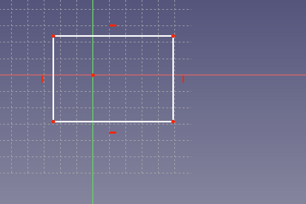
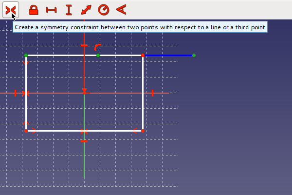
Прямоугольник должен оставаться в центре системы координат. Для этого к горизонтальной линии добавлено ограничение симметрии. Для этого нужно выбрать сначала две вершины горизонтальной линии, а затем вертикальную ось системы координат. Ограничение симметрии добавляется, щёлкнув по кнопке ![]() . То же самое делается для вертикальной линии, но теперь в качестве оси симметрии выбрана горизонтальная ось. На рисунке ниже показан результат. Прямоугольник теперь остается в центре и может быть только изменен в размерах, но не перемещён.
. То же самое делается для вертикальной линии, но теперь в качестве оси симметрии выбрана горизонтальная ось. На рисунке ниже показан результат. Прямоугольник теперь остается в центре и может быть только изменен в размерах, но не перемещён.
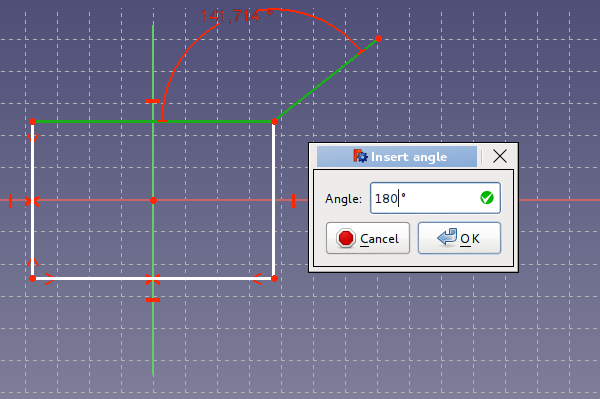
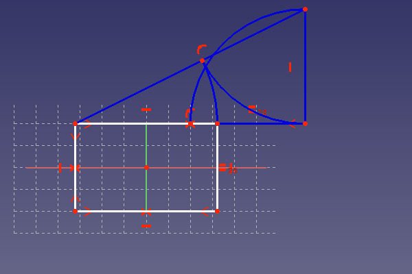
Это была заготовка для прямоугольника. Верхняя горизонтальная линия должна представлять собой расстояние AS при построении золотого сечения. Дополнительная линия нужна для обозначения расстояния SB. Она рисуется немного наискосок, как показано ниже. Это позволяет избежать автоограничения по горизонтали. Эту линию следует ограничить углом 180°, чтобы избежать существования нескольких решений для построенной комбинации ограничений. Если линия нарисована с горизонтальным ограничением, то впоследствии при добавленом ограничении с углом 180° скетчер будет жаловаться. В этом случае горизонтальное ограничение нужно убрать. На рисунке показано, как добавить угловое ограничение, выделив две линии и щёлкнув по ![]() . После того как линия добавлена, часто рекомендуется провести по ней мышью. Это позволит легко определить, не привязана ли линия к другим нарисованным элементам. Если линия не соединена правильно с другими линиями, могут возникнуть проблемы на последующих этапах построения детали.
. После того как линия добавлена, часто рекомендуется провести по ней мышью. Это позволит легко определить, не привязана ли линия к другим нарисованным элементам. Если линия не соединена правильно с другими линиями, могут возникнуть проблемы на последующих этапах построения детали.
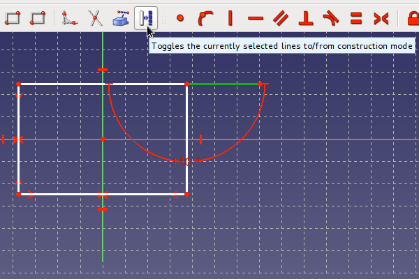
Последняя линия не является частью прямоугольника. Поэтому необходимо преобразовать её во вспомогательную линию. Выделите линию и щёлкните по кнопке ![]() , чтобы преобразовать её.
, чтобы преобразовать её.
Теперь линия имеет синий цвет, как видно ниже. В описании золотого сечения из Википедии требуется линия, равная половине расстояния AB. Чтобы получить точку отсчёта для этого, на линии устанавливается дополнительная вершина с помощью инструмента ![]() . Это показано ниже.
. Это показано ниже.
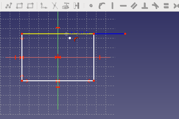
Точка отсчёта должна находиться в середине расстояния AB. Для этого сначала выбираются две конечные точки отрезка AB, а затем - третья центральная точка. Когда все три точки выбраны в правильной последовательности, можно установить ограничение симметрии, щёлкнув по кнопке ![]() , как показано ниже.
, как показано ниже.
На рисунке ниже показана уже вторая сторона BC треугольника построения. Эта линия была нарисована, как описано выше, и преобразована во вспомогательную линию. Эта линия должна иметь вертикальное ограничение, как видно на рисунке. Этого можно легко добиться, проведя линию почти вертикально. Если линия почти вертикальна, символ вертикального ограничения будет показан и установлен скетчером при завершении линии в этом состоянии.
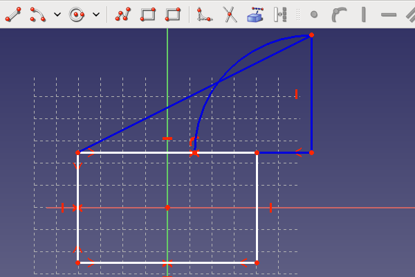
Отрезок BC должен иметь половину длины AB. Для этого имеется только опорная точка, поэтому ограничение равенства не может быть использовано. Ограничение равенства требует наличия линии с такой длиной в качестве опорной точки, которой нет в построении. Поэтому для определения длины BC используется классическая дуга. На рисунке ниже показан чертёж дуги. Используется инструмент дуги ![]() . Сначала задается центральная точка B. Точка должна быть видна под дугой-инструментом, если щёлкнуть по B. Часто дугу-инструмент приходится располагать не прямо над целевой точкой, а немного ниже, чтобы точка совпадения была видна. Во-вторых, радиус дуги задаётся путём установки следующей точки на опорную точку. Последняя точка дуги устанавливается в окрестности точки C. Важно, чтобы первые две точки были привязаны к C и центральной точке. Это следует проверить, перетащив дугу после её завершения.
. Сначала задается центральная точка B. Точка должна быть видна под дугой-инструментом, если щёлкнуть по B. Часто дугу-инструмент приходится располагать не прямо над целевой точкой, а немного ниже, чтобы точка совпадения была видна. Во-вторых, радиус дуги задаётся путём установки следующей точки на опорную точку. Последняя точка дуги устанавливается в окрестности точки C. Важно, чтобы первые две точки были привязаны к C и центральной точке. Это следует проверить, перетащив дугу после её завершения.
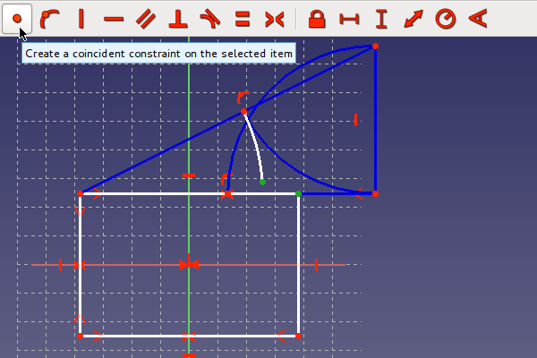
Чтобы определить длину BC, линия должна заканчиваться на дуге. Для этого нужно установить ограничение совпадения между последней точкой дуги и точкой C, как показано ниже. Выделите обе точки и щёлкните по кнопке создания совпадения ![]() .
.
На следующем рисунке показан готовый треугольник. Гипотенуза AC уже нарисована и преобразована во вспомогательную линию.
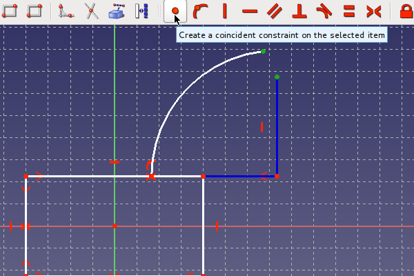
Теперь необходимо построить шаг 2 из описания Википедии. Нужно построить вторую дугу с центральной точкой в точке C и начальной точкой в точке B. Последняя точка должна заканчиваться на гипотенузе, как показано на рисунке ниже.
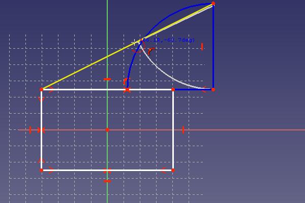
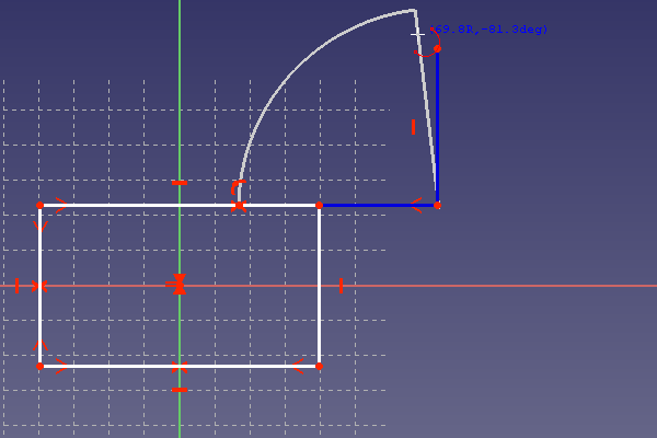
Нарисованная дуга была преобразована во вспомогательную линию. Теперь шаг 3 из Википедии начинается с построения последней дуги, как показано на рисунке ниже. Радиус этой дуги должен быть задан с помощью построенной выше точки на гипотенузе. Последняя точка обычно не заканчивается на углу прямоугольника. Но это не проблема, так как она будет исправлена позже. Последняя точка может располагаться так, как показано ниже.
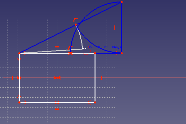
Теперь необходимо сделать последний шаг, чтобы горизонтальная линия прямоугольника была равна расстоянию AS. Это показано ниже путём установки ограничения совпадения между концом последней дуги и углом прямоугольника.
Теперь нужно сделать вертикальную линию длиной, равной расстоянию SC. Для этого установите ограничение равенства, нажав кнопку ![]() , как показано ниже.
, как показано ниже.
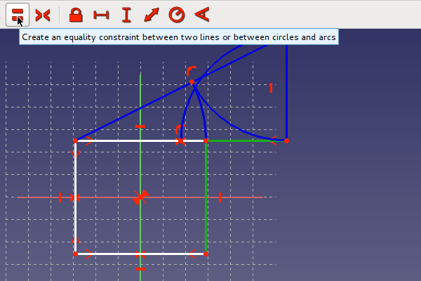
На следующем рисунке изображен прямоугольник с отношением длин сторон, равным золотому сечению. У прямоугольника должна остаться только одна степень свободы. Поэтому при перетаскивании он должен только изменять свой размер, но не двигаться. Если требуется определенный размер одной из сторон, к ней может быть добавлено ограничение по длине. В остальном эскиз готов и может быть закрыт. После этого в окне FreeCAD должен быть виден только прямоугольник.
Упражнение: упругий эскиз
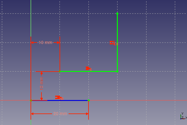
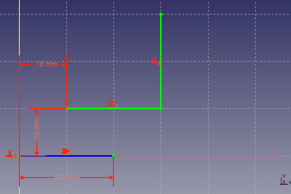
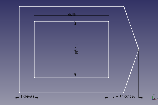
В приведенном выше примере были представлены вспомогательные линии. Теперь мы обсудим некоторые важные моменты для создания устойчивых эскизов. Вот упражнение, позволяющее попрактиковаться в работе с эскизом. Задача состоит в том, чтобы сделать эскиз для чего-то вроде специальной рамы, как показано ниже.
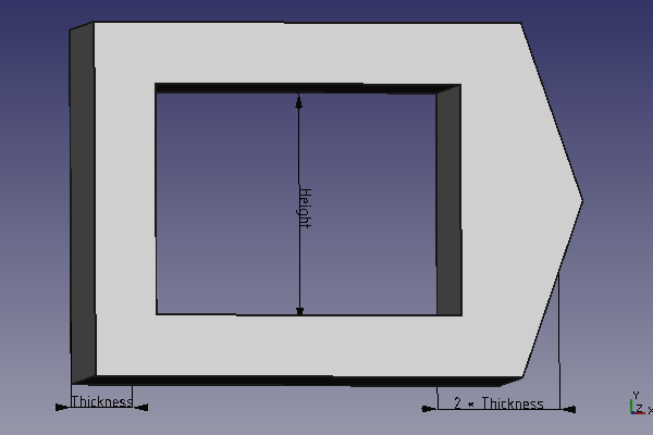
Для построения каркаса необходимо всего три измерения. Чтобы было проще менять размеры, ограничения можно переименовать в какое-нибудь запоминающееся. Просто выделите ограничение в списке и нажмите <F2>. Ограничение можно назвать, например, "Толщина". На рисунке ниже показаны размеры. Пик с правой стороны должен иметь толщину, в два раза превышающую толщину стенки.
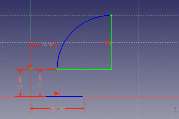
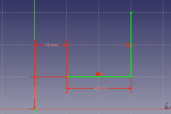
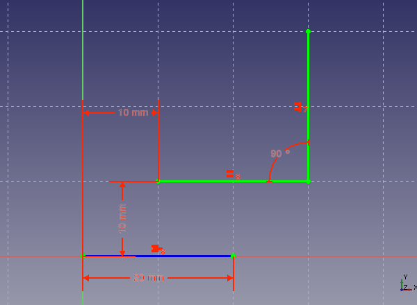
Эскиз должен выглядеть так, как задумано, и после изменения ключевых размеров, например, до 2000 мм и обратно до 30. Для достижения этой цели вам может понадобиться использовать угловые ограничения в некоторых местах. На рисунке ниже показан эскиз, который не был устойчив к таким изменениям. Теперь он непригоден для использования. Чтобы вернуть исходное состояние, можно воспользоваться кнопкой отмены ![]() .
.
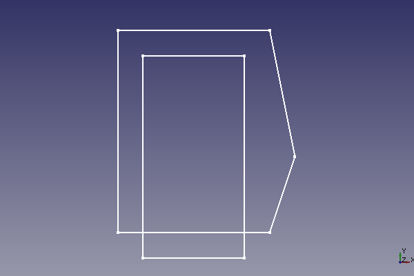
Приведенный выше эскиз непригоден для использования в Верстаке ПроектнаяДеталь (PartDesign). Допускается только профиль без пересекающихся линий. Линии построения могут пересекаться. Они не используются для создания твёрдых тел.
Одно из основных применений Скетчера - построение деталей в верстаке ПроектнаяДеталь. Уже существующая геометрия может быть использована подобно строительным линиям. Поскольку в этом руководстве основное внимание уделяется базовой функциональности скетчера, посмотрите здесь, как использовать внешнюю геометрию: Скетчер Внешняя геометрия
Эта страница получена от https://wiki.freecad.org/Sketcher_Tutorial