This documentation is not finished. Please help and contribute documentation.
GuiCommand model explains how commands should be documented. Browse Category:UnfinishedDocu to see more incomplete pages like this one. See Category:Command Reference for all commands.
See WikiPages to learn about editing the wiki pages, and go to Help FreeCAD to learn about other ways in which you can contribute.
|
|
| Menu location |
|---|
| SheetMetal → Make Forming in Wall |
| Workbenches |
| SheetMetal |
| Default shortcut |
| M F |
| Introduced in version |
| - |
| See also |
| None |
Description
The ![]() SheetMetal Forming command creates an embossed shape in a SheetMetal wall using a separate solid object.
SheetMetal Forming command creates an embossed shape in a SheetMetal wall using a separate solid object.
The back side face of the solid defining the shape, and the face to be embossed are used to position and orient the solid, i.e. their local coordinate systems will have the same origin and the same orientation by default. The angle around the Z-axis and offsets in the X, Y, and Z direction can be altered by changing their values in the Property View.
A sketch can be added to multiply and distribute the embossed shape in regular or irregular patterns (using the center points of circles or arcs).
A small selection of features that can be created:
Dimples, louvres, drawn cutouts, bridges
Usage
Make sure that the body containing the object to be embossed is the active body. If required double-click it in the Tree View.
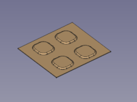
Dimple
- Select the face of the SheetMetal object to be embossed.
- Hold down the Ctrl key (or the Command key on macOS).
- Add the bottom face (back side) of the solid defining the shape to the selection.
- Release the Ctrl key (or the Command key).
- There are several ways to invoke the command:
- Press the
 Make Forming in Wall button.
 - Select the SheetMetal → Make Forming in Wall option from the menu.
- Right-click in the Tree View or the 3D View and select the SheetMetal → Make Forming in Wall option from the context menu.
- Use the keyboard shortcut: M then F.
- Press the
- The Forming tool parameters Task Panel opens (introduced in version 0.5.00).
- Optionally select new faces/edges.
- Press the Update button to finish the selection and display the changes.
- Press the OK button to finish the command and close the Task Panel.
- A WallForming object will be created at the center of the selected face to be embossed.
- Optionally adjust the parameters in the Property View.
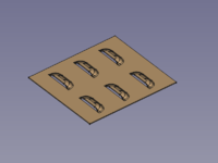
Louvre
- Select the face of the SheetMetal object to be embossed.
- Hold down the Ctrl key (or the Command key on macOS).
- Add the bottom face (back side) of the solid defining the shape to the selection.
- Add a side face adjoined the bottom face to indicate the position of the cut to the selection.
- Release the Ctrl key (or the Command key).
- Invoke the command and follow the steps as described above.
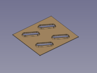
Bridge
- Select the face of the SheetMetal object to be embossed.
- Hold down the Ctrl key (or the Command key on macOS).
- Add the bottom face (back side) of the solid defining the shape to the selection.
- Add a side face adjoined the bottom face to indicate the position of the first cut to the selection.
- Add the opposite side face adjoined the bottom face to indicate the position of the second cut to the selection.
- Release the Ctrl key (or the Command key).
- Invoke the command and follow the steps as described above.
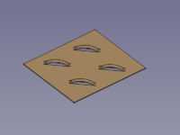
Drawn Cutout
- Select the face of the SheetMetal object to be embossed.
- Hold down the Ctrl key (or the Command key on macOS).
- Add the bottom face (back side) of the solid defining the shape to the selection.
- Add the top face opposite the bottom face to mark the area to be cut open to the selection.
- Release the Ctrl key (or the Command key).
- Invoke the command and follow the steps as described above.
Multiply and Pattern
To muliply and pattern the embossed feature a sketch containing circles and arcs can be added to the WallForming object's property DatiSketch. This pattern sketch must be coplanar with the face to be embossed.
The centerpoints of the circles or arcs are used to provide positions to put instances of the embossed feature; they don't influence the instances' orientation.
The orientation still depends on the orientation of the first selected face.
Adding Fillets
- Switch to the
 PartDesign workbench
 - Select an edge on the upper side of the SheetMetal object to receive a fillet
- Activate the
 PartDesign Fillet command using one of the following:
- The PartDesign Fillet button.
- The PartDesign → Apply a dress-up feature → Fillet menu option.
- The
- Set the Fillet object's DatiRefine property to
true. This is important for the next fillet. - Select an edge on the bottom side of the SheetMetal object to receive a fillet.
- Activate the PartDesign Fillet command (see above)
Notes
The embossed geometry is not restricted to planar walls and cylindrical connections and so after such a geometry is applied to a SheetMetal object the object is no longer unfoldable.
The forming can be deactivated (by setting the property DatiSuppress Feature to true) to unfold the object, but following fillets lose their defining edges and show an error when the forming is reactivated.
Forming and fillets should be the last steps in creating a SheetMetal object.
Properties
See also: Property View.
A SheetMetal WallForming object is derived from a Part Feature object or, if it is inside a PartDesign Body, from a PartDesign Feature object, and inherits all its properties. It also has the following additional properties:
Data
Parameters
- DatiSuppress Feature (
Bool): "Suppress Forming Feature". Default value isfalse. - Datiangle (
Angle): "Tool Position Angle". Default angle:0,00°. - Datibase Object (
LinkSub): "Base Object". Link to the planar face to be embossed. - Datioffset (
VectorDistance): "Offset from Center of Face". Default:[0,00 mm, 0,00 mm, 0,00 mm]. - Datithickness (
Distance): "Thickness of Sheetmetal". Thickness of the Dati (hidden)Base Feature. - Datitool Object (
LinkSub): "Forming Tool Object". Link to the planar face used to position the Forming Tool
Parameters1
- DatiSketch (
Link): "Point Sketch on Sheetmetal". Link to the sketch containing information how to multiply and distribute instances of the Forming Tool. (Center points of circles and arcs are used to create and position these instances)
Example


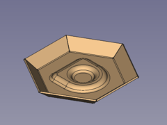
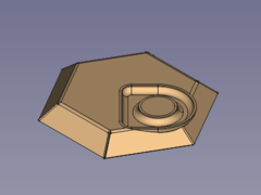
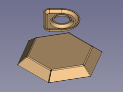
A hexagon bowl with embossed centre
Preparation
This bowl is made of a folded sheet metal object with a shape embossed, both have to be prepared in advance.
No need to work with coplanar sketches here.
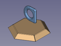
SheetMetal bowl and embossing object
Workflow
- Select the wall of the SheetMetal object to be embossed
- Select the back side of the shape defining solid
(Remember both the object to be embossed and the shape defining solid must be selected. Activate the multi-select method appropriate for your operating system: Control/Command.)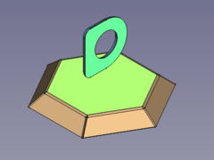
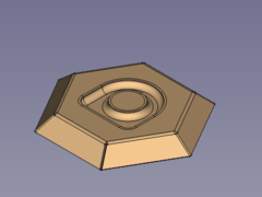
- Press the Make Forming in Wall button
or use the keyboard shortcut: M then F
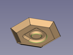
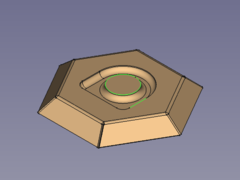
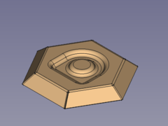
- Fillet the sharp edges:
- Flip the bowl and select one or more edges for the smaller inner radii
- Press the PartDesign Fillet button
 -->
--> 
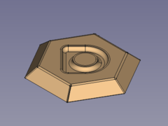
- Flip the bowl again and select one or more edges for the bigger outer radii
- Press the PartDesign Fillet button
 -->
--> 
Done!
- Alter orientation and position (should be done before filleting)
- Activate the WallForming object in the Tree View
- Set the value of the property Datiangle to e.g. 45°
- Set the value of the property Datioffset, x to e.g. greater than 0
Here it is plain to see that it doesn't make sense to move the embossed geometry outside the selected wall.
- Setting the value of the property Datioffset, z to e.g. greater than 0 isn't any better:
At least the FreeCAD doesn't crash when a part has two bodies...
- Activate the
- Some hints
- The height of the defining solid determines the depth of the embossed shape.
That means changing the parameter offset, z to alter the depth won't deliver expected results. - The embossed geometry is made of a shell object i.e. it has a constant thickness.
And so the defining solid has to be offsetable, otherwise the tool will fail to create the emboss. - If the outer edges are filleted first it may rip the object into several pieces when the radii are set too large.
- The height of the defining solid determines the depth of the embossed shape.
Questa pagina è recuperata da https://wiki.freecad.org/SheetMetal_Forming