This documentation is not finished. Please help and contribute documentation.
GuiCommand model explains how commands should be documented. Browse Category:UnfinishedDocu to see more incomplete pages like this one. See Category:Command Reference for all commands.
See WikiPages to learn about editing the wiki pages, and go to Help FreeCAD to learn about other ways in which you can contribute.
|
|
| Posizione nel menu |
|---|
| SheetMetal → Add Bend |
| Ambiente |
| SheetMetal |
| Avvio veloce |
| None |
| Introdotto nella versione |
| - |
| Vedere anche |
| Nessuno |
Descrizione
Lo strumento di piegatura di SheetMetal ![]() crea una piega sul bordo selezionato.
crea una piega sul bordo selezionato.

A flange usually consists of a 90° cylindrical bend and a planar strip (wall).
![]()
Two selected edges → two flanges
It is called a hem instead if the bend is roughly 180°.
![]()
Two selected edges → two mitered hems
Utilizzo
Per aggiungere una piega:
- Passare nell'ambiente
 SheetMetal.
 - Iniziare con una lastra di base o un foglio, selezionare uno o più bordi che devono ricevere una piega.
- Cliccare sullo strumento
 Bend per aggiungere una piega.
Task Panel
A Task Panel with four tabs was introduced in 0.6.00
Double-click an existing Bend object in the Tree View to re-open the Task Panel and edit the parameters.
General

- Select: Changes the amount of edges in the base Object property.
- Length: Sets the length property.
 Reverse the wall: Toggles the invert property.
- Length mode: Sets the Length Spec property.
- Bend radius: Sets the radius property.
- Bend angle: Sets the angle property.
 Face reference: Switches the Bend angle option to read-only mode and displays two further options:
- Reference: Awaits a face to be selected in the 3D View and links it to the Angle Face Reference property.
- Relative angle: Sets the Relative Angle To Ref property.
- Wall position: Sets the Bend Type property.
- If set to
Offsettwo further options are available:
- Offset: Sets the offset property.
- Face reference: Switches the Offset option to read-only mode and displays two further options:
- Reference: Awaits a face to be selected in the 3D View and links it to the Offset Face Reference property.
- Offset position: Sets the Offset Type property.
- If set to
Offsetanother option is available:
- Offset from reference: Sets the Offset Type Offset property.
- If set to
- If set to
- Unfold: Toggles the unfold property.
Offsets

- Gap A: Sets the gap1 property.
- Gap B: Sets the gap2 property.
- Extend A: Sets the extend1 property.
- Extend B: Toggles the extend2 property.
- Rectangle and Round radio buttons: Toggle relief Type property.
- Width: Sets the reliefw property.
- Depth: Toggles the reliefd property.
Miter

- Auto Miter: Toggles the Auto Miter property.
- If checked:
- Minimum Gap: Sets the minGap property.
- Max Extend Distance: Sets the max Extend Dist property.
- If unchecked:
- Angle 1: sets the miterangle1 property.
- Angle 2: sets the miterangle2 property.
Perforation

- Perforate: Toggles the Perforate property.
- If checked:
- Angle: Sets the Perforation Angle property.
- Initial Cut Length: Sets the Perforation Initial Length property.
- Max Cut Length: Sets the Perforation Max Length property.
- Max Tab Length: Sets the Nonperforation Max Length property.
Notes
Nota: questo ambiente non dispone di uno strumento per creare una piastra di base, quindi è necessario avviare il modello con uno dei seguenti metodi:
- Metodo 1:
 Cubo di Part
 - Metodo 2: Un solido estruso realizzato con
 Estrudi di Part da un:
 Rettangolo di Draft o una
 Polilinea di Draft o uno
 Schizzo
- Usare
 Spessore di Part per creare un solido (Tipicamente con il valore dello spessore della lamiera.)
- Metodo 3:
 Corpo di PartDesign contenente un
 cubo additivo o un
 pad prodotto da uno schizzo.
- Usare Spessore di Part per creare un solido (Tipicamente con il valore dello spessore della lamiera.)
- Metodo 1:
Proprietà
See also: Property View.
A SheetMetal Bend object is derived from a Part Feature object or, if it is inside a PartDesign Body, from a PartDesign Feature object, and inherits all its properties. It also has the following additional properties:
Dati
Parameters
- Datiangle: Angolo di piega.
- Datiextend1: Estende il lato sinistro.
- Datiextend2: Estende il lato destro.
- Datigap1: Distanza sul lato sinistro del lembo piegato dall'angolo della forma base.
- Datigap2: Distanza dall'angolo dal lato destro.
- Datiinvert: Inverte la direzione della piega.
- Datilength: Lunghezza della parte piegata .
- Datimiterangle1: Piega con un angolo di mitra sul lato sinistro.
- Datimiterangle2: Piega con un angolo di mitra sul lato destro.
- Datiradius: Raggio di curvatura della piega.
- Datirelief Type: Gole di scarico Rettangolari o arrotondate. Abilitato solo quando è impostato un valore di gap.
- Datireliefd: Profondità della gola di scarico. Abilitata solo quando è impostato un valore di gap.
- Datireliefw: Larghezza della gola di scarico. Abilitata solo quando è impostato un valore di gap.
- Datikfactor: Fattore K (noto anche come fattore neutro) per la curva. Utilizzato per calcolare la tolleranza di piegatura durante lo sviluppo.
- Datiunfold: False (predefinito) o True. Se è vero, dispiega la curva.
Parameters Ex
- DatiAngle Face Ref Mode (
Bool): "Enable face reference for angle". Default:true. introduced in 0.7.11 and removed before 0.7.58 - DatiAngle Face Referene (
LinkSub): "Face reference for angle". Default:true. introduced in 0.7.11 - DatiAuto Miter (
Bool): "Enable Auto Miter". Default:true. - DatiOffset Face Ref Mode (
Bool): "Enable face reference for offset". Default:true. introduced in 0.7.11 and removed before 0.7.58 - Dati Offset Face Reference (
LinkSub): "Face reference for offset". Default:true. introduced in 0.7.11 - DatiOffset Type (
Enumeration): "Offset Type". introduced in 0.7.11- Values:
Material Outside,Material Inside(default),Thickness Outside,Offset.
- Values:
- DatiOffset Type Offset (
Distance): "Works when offset face reference is on. It offsets by a normal distance from the offset reference face". Default:0.00. introduced in 0.7.11 - DatiRelative Angle To Ref (
Angle): "Relative angle to the face reference". Default:0.00. introduced in 0.7.11 - DatiSuppl Angle Ref (
Bool): "Supplementary angle reference". Default:true. introduced in 0.7.11 - Datikfactor (
FloatConstraint): "Location of Neutral Line. Caution: Using ANSI standards, not DIN.".
Default:0,50. K factor (also known as neutral factor) for the bend. Used to calculate bend allowance when unfolding. - Datimax Extend Dist (
Length): "Auto Miter maximum Extend Distance". Default:5,00 mm. - Datimin Gap (
Length): "Auto Miter Minimum Gap". Default:0,20 mm. - Datimin Relief Gap (
Length): "Minimum Gap to Relief Cut". Default:1,00 mm. - Datioffset (
Distance): "Offset Bend". Default:0,00 mm. - Datiunfold (
Bool): "Shows Unfold View of Current Bend". Default:false
trueunfolds the bend.
Parameters Ex2
- DatiSketch (
Link): "Sketch Object". - Datisketchflip (
Bool): "Flip Sketch Direction". Default:false. - Datisketchinvert (
Bool): "Invert Sketch Start". Default:false.
Parameters Ex3
- DatiLength List (
FloatList): "Length of Wall List". Default:[10.00]. - Datibend AList (
FloatList): "Bend Angle List". Default:[90.00].
Parameters Miterangle
- Datimiterangle1 (
Angle): "Bend Miter Angle from Left Side". Default angle:0,00°. - Datimiterangle2 (
Angle): "Bend Miter Angle from Right Side". Default angle:0,00°.
Parameters Perforation
- DatiNonperforation Max Length (
Length): "Non-Perforation Max Length". Default:5 mm. - DatiPerforate (
Bool): "Enable perforation". Default:false. - DatiPerforation Angle (
Angle): "Perforation Angle". Default:0 °. - DatiPerforation initial Length (
Length): "Initial Perforation Length". Default:5 mm. - DatiPerforation Max Length (
Length): "Perforation Max Length". Default:5 mm.
Parameters Relief
- DatiRelief Factor (
Float): "Relief Factor". Default:0,70. - DatiUse Relief Factor (
Bool): "Use Relief Factor". Default:false. - Datirelief Type (
Enumeration): "Relief Type".Rectangle(default),Round. Enabled only when a gap value is set. - Datireliefd (
Length): "Relief Depth". Default:1,00 mm. Enabled only when a gap value is set. - Datireliefw (
Length): "Relief Width". Default:0,80 mm. Enabled only when a gap value is set.
Example
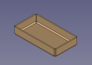
A simple tray
Preparation
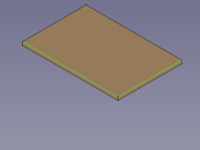
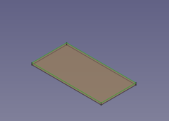
This tray is made of a rectangular blank with walls added to its outline edges. And so one outline sketch for the blank has to be prepared in advance.
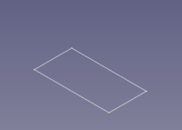
Just a rectangular outline
Workflow
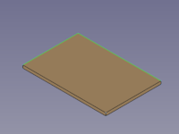
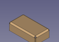
- Create a blank
- Select the outline sketch
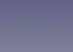
- Press the
 Make Base Wall button
or use the keyboard shortcut: C then F
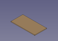
(The blank is padded in z direction
- Select the outline sketch
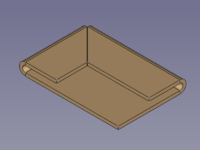
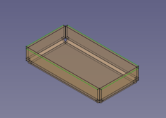
- Add walls to the outline edges
- Select the blank's outline edges
- Press the
 Make Wall button
or use the keyboard shortcut: W
- If the fold is 90° down set the value of invert property to true to reverse the direction (and length to a lower value for smaller walls)

- Select the blank's outline edges
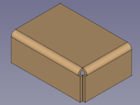
- Add some more walls
- Select the tray's upper outside edges
- Press the Make Wall button
or use the keyboard shortcut: W
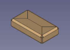
- The walls are a bit too long (but nicely trimmed) and so the length property has to be set to a lower value
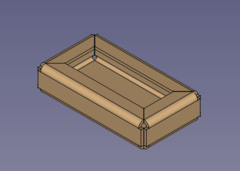
- If you like the folds swing outward set the invert value to true
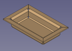
- Select the tray's upper outside edges
Done!
Questa pagina è recuperata da https://wiki.freecad.org/SheetMetal_AddWall