|
|
| Menu location |
|---|
| Part → Sweep |
| Workbenches |
| Part |
| Default shortcut |
| None |
| Introduced in version |
| - |
| See also |
| Part Loft |
Description
The ![]() Part Sweep command creates a face, a shell, or a solid shape from one or more profiles (cross-sections) distributed along a spine.
Part Sweep command creates a face, a shell, or a solid shape from one or more profiles (cross-sections) distributed along a spine.
The Part Sweep command is similar to ![]() Part Loft with the addition of a spine.
Part Loft with the addition of a spine.
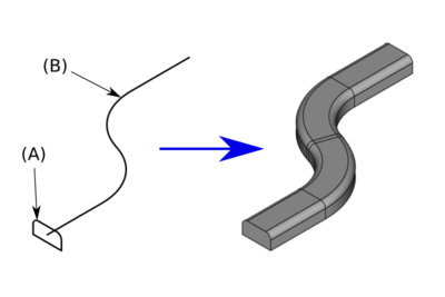
A solid sweep generated from a single profile (A) distributed along a spine (B)
Usage
- There are several ways to invoke the command:
- Press the
 Sweep button.
 - Select the Part → Sweep option from the menu.
- Press the
- The Sweep task panel opens.
- In the Available profiles list on the left select a profile and click on the right arrow to place it in the Selected profiles list on the right.
- Repeat if more than one profile is desired.
- The up and down arrows will reorder the list on the right. But this has no impact on the result. The position of the profiles along the spine determines in which order they are used.
- Click on the Sweep Path button, then choose either mode of selection:
- Segment selection: select one or more contiguous edges in the 3D View (press CTRL for multiple selection) and click Done. The sweep will only be generated along the selected edges.
- Complete path selection: switch to the Tree View, select the object to be used as spine, switch back to the task panel and click Done. The sweep will be generated along all the contiguous edges found in the object.
- Define options Create solid and Frenet.
- Click OK to close the task panel.
- A Sweep object is created.
Accepted geometry
- Profiles: can be a point (vertex), line (edge), wire or face. Edges and wires may be either open or closed. There are various Limitations, see below. Sometimes, it's not sufficient to properly align the profile with the path. To make the command work correctly, it might also be necessary to attach the profile to the path. If the profile's sketch is attached to the wrong end of the path's edge, change DataMap Path Parameter from 0 to 1.
- Path: can be a line (edge) or a series of connected lines, a wire or various Part Workbench objects, Draft Workbench objects or a Sketch. The path may be either open or closed.
- App Link objects linked to the appropriate object types and App Part containers with the appropriate visible objects inside can also be used as profiles and paths.
Options
Create solid
If "Create solid" is set to "true", FreeCAD creates a solid, provided the profiles are closed; if set to "false", FreeCAD creates a face or a shell for either open or closed profiles.
Frenet

The "Frenet" property controls how the profile orientation changes as it follows along the sweep path. If "Frenet" is "false", the orientation of the profile is kept consistent from point to point. The resulting shape has the minimum possible twisting. Unintuitively, when a profile is swept along a helix, this results in the orientation of the profile slowly creeping (rotating) as it follows the helix. Setting "Frenet" to true prevents this.
If "Frenet" is "true" the orientation of the profile is based on the local curvature and tangency vectors of the path. This keeps the orientation of the profile consistent when sweeping along a helix (because the curvature vector of a straight helix always points to its axis). However, when path is not a helix, the resulting shape can have strange looking twists sometimes. For more information, see Frenet Serret formulas.
Transition
"Transition" sets the transition style of the Sweep at non-tangential joints in the path. The property is not exposed in the task panel and can be found in the properties after the Sweep has been created.
Properties
See also: Property View.
A Part Sweep object is derived from a Part Feature object and inherits all its properties. It also has the following additional properties:
Data
Sweep
- DataSections (
LinkList): lists the sections used. - DataSpine (
LinkSub): spine (path) to sweep along. - DataSolid (
Bool): true or false (default). True creates a Solid. - DataFrenet (
Bool): true or false (default). True uses Frenet algorithm. - DataTransition (
Enumeration): transition mode. Options are Transformed, Right corner or Round corner.
Limitations
Vertex or point
A vertex or point may only be used as the first and/or last profile.
For example:
- You cannot Sweep from a circle to a point, to an ellipse.
- You can however Sweep from a point to a circle to an ellipse to another point.
Profiles
In one Sweep, all profiles (lines wires etc.) must be either open or closed.
For example:
- FreeCAD cannot Sweep between a Part Circle and a Part Line.
Sketches
- The profile may be created with a sketch. However only valid sketches will be available for selection in the task panel.
- The sketch must contain only one open or closed wire or line (can be multiple lines, if those lines are all connected as they are then a single wire).
Draft Workbench objects
A profile can be a Draft Workbench object.
The following objects can be valid profiles:
- Point
- Line, Wire
- B-spline, Bézier Curve
- Circle, Ellipse
- Rectangle, Polygon
Part Workbench objects
A profile can be a Part object created with the Part Primitives command.
The following objects can be valid profiles:
- Point (Vertex)
- Line (Edge)
- Helix, Spiral
- Circle, Ellipse
- Regular Polygon
- Plane (Face)
Links
- A Sweep is often used to create threads for screws, see the Thread for Screw Tutorial for more information.
This page is retrieved from https://wiki.freecad.org/Part_Sweep