|
|
| Description |
|---|
| Tool utility to create Points, Axis, Planes...and other usefull functions. Macro version: 2019-05 Last modified: 2019-05-01 FreeCAD version: All Download: ToolBar Icon Author: rentlau_64 |
| Author |
| rentlau_64 |
| Download |
| ToolBar Icon |
| Links |
| Macros recipes How to install macros How to customize toolbars |
| Macro Version |
| 2019-05 |
| Date last modified |
| 2019-05-01 |
| FreeCAD Version(s) |
| All |
| Default shortcut |
| None |
| See also |
| None |
Description
Tool utility to create:
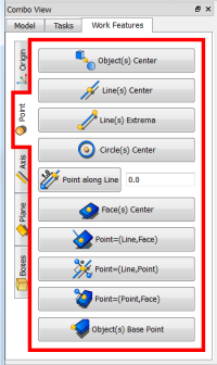
- Points (mid points, center of circle, center of object(s)...),
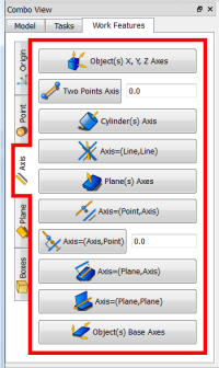
- Axes (from 2 points, Normal of a plane...),
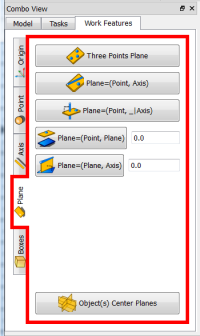
- Planes (from 3 points, from one axis and a point...)
- And many other useful features to facilitate the creation of your project. This utility is up next in the combo view with "Work Features" label.

WorkFeatures
Uses
Work Features
-
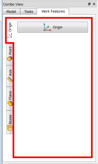
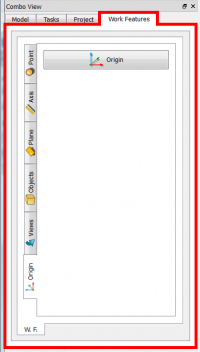 After activating Work Features, the tool moves to the left in the window Combo view.
 -
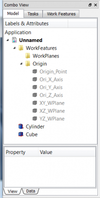 Each use and each Tag that corresponds to a function group is a group created in the name of Tag used. The Axis, Point and Planes origin are directly keyed to hidden.
 -
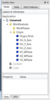 You can ENTERING AND USING common commands to make visible the created function.
Example key Space or select your object and click right of mouse and click "Hide selection" or "Show selection".
Origin Tab
 |
|
Points Tab
 |
|
Axis Tab
 |
|
Plane Tab
 |
|
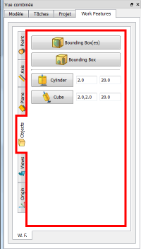
Objects Tab
 |
|
Views Tab
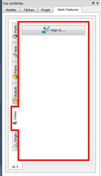 |
|
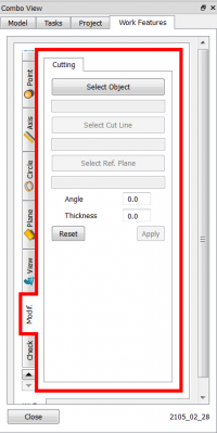
Modif. Tab
 |
|
Check. Tab
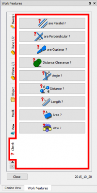 |
|
Script
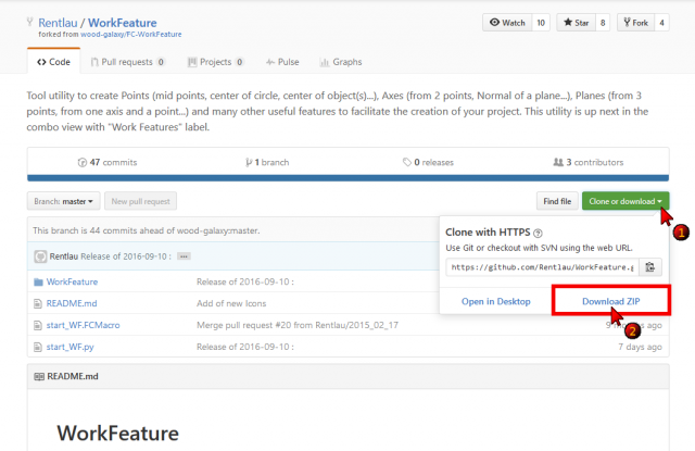
After downloading the file compressed here
ToolBar Icon 
Download the latest version on GitHub , you must unzip the zip and copy all the files in your macro directory.
PS: This macro is still in development please visit this page regularly to be sure to have the latest version.
Use ![]() Addons installer, Menu → Tools → Addon installer for easy installation of WorkFeatures and other interesting macros.
Addons installer, Menu → Tools → Addon installer for easy installation of WorkFeatures and other interesting macros.
Here for How to install macros detailed
Examples
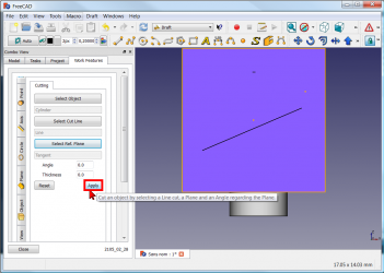
Cutting tools
Setting of the Cutting tools: Select an object to cut, a cutting line and a reference Plane. Angle is an angle between the cutting Plane and the Ref. Plane. Thickness is the wide of the of the cutting Plane.
-
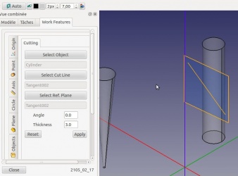 Here we have selected a cylinder.
 -
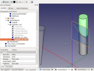 The result will be : the cylinder is then cut in two parts!
Example the practice
-
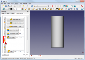 Select the Tab Plane
 -
 and click the Plane button
(you can change the dimensions of the plane (Default: 10 x 10)).
-
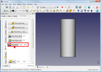
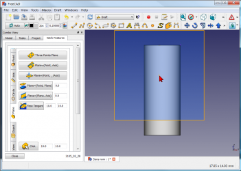 click you work object. The plane is created tangent of the object (here a cylinder)
 -
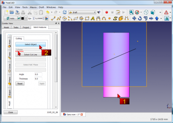 click the Tab Modif, and
1 : click your object for cutting
2 : click the Select object button (here the cylinder and then name is displayed)
-
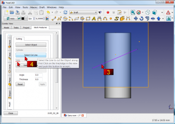 3 : click your line for cutting your cylinder
4 : click the Select Cut Line (then name is displayed) -
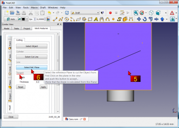 5 : click the work plane
6 : click the Select Ref. Plane button (then name is displayed)
-
 click the Apply button
 -
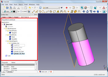 The operation is completed and all operations are preserved.
-
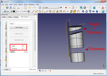 you can also give Angle and Thickness for your cut.
Concentric constraint between two non cylindrical parts
| How to Constraint Between two non cylindrical parts. 1 : The original object to modify. 2 : Objective center two square tubes. 3 : Select the first object and in the menu Axis 1/2 click "Object(s)" X, Y, Z Axes. 4 : Same procedure for the second object. 5 : Click on button Draw style and onto "Wireframe", 6 : for clarify the view. 7 : Select the object to center and his axis created. 8 : Click the button Draft Move 9 : and select the first axis to move on the second axis. 10 : Restore normal view with on button Draw style and onto As is. 11 : Click the first object moved and correct the position with "Combo view > Data > Placement". 12 : Select the object created by WorkFeature (contener axis) and delete it. 13 : The object vanished. 14 : The result. |
Rotation Object
-
 Click the image for see the animation.
Plane on face tangent
-
 Click the image for see the animation.
Click the object, click the Face tangent button, click the point on face for create the plane.
Links
The forum discussion MACRO:Work Feature 2014_12
Latest version
Icons :

Sources :
On GitHub : /github.com/Rentlau/WorkFeature-WB.git
Date 2019-05-01 (YYYY-MM-DD)
20/01/2019
08/03/2015 : WF_2015_03_08 - Circle cut added - Are Parallel, Are Perpendicular, Are Coplanar added
17/02/2015 : WF_2015_02_17 - Circle and Ellipse Tab added - Cutting tab added
25/01/2015 : WF_2015_01_25.zip add Object Cylinder Cube
18/01/2015 : WF_2015_01_18.tar.gz add plane and face to view
28/12/2014 : WorkFeatures_2014_12_28.zip
27/12/2014 : WF_2014_12_27.zip
This page is retrieved from https://wiki.freecad.org/Macro_WorkFeatures