|
|
| Menu location |
|---|
| Mesh → Mesh From Shape by Gmsh |
| Workbenches |
| FEM |
| Default shortcut |
| None |
| Introduced in version |
| - |
| See also |
| FEM tutorial |
| Solvers |
|---|
| All |
Description
For a finite elements analysis the geometry needs to be discretized into a FEM Mesh. This command uses the software Gmsh (which needs to be installed on the system) to generate the mesh.
Depending on your operating system and your installation package, Gmsh might be bundled with FreeCAD or not. For further information see FEM Install.
Usage
- Select the shape you want to analyze. For volume FEM this needs to be a solid or compsolid. A compsolid is necessary if your part is made from multiple materials (a compsolid can be created with the BooleanFragments command).
- There are several ways to invoke the command:
- Press the
 Mesh From Shape by Gmsh button.
 - Select the Mesh → Mesh From Shape by Gmsh option from the menu.
- Press the
- Optionally, edit the minimum and maximum element size (the default setting often creates meshes that are too coarse). You can also change the element dimension (but the default From shape setting is normally sufficient) and order.
- Click the Apply button and wait for the generation of the mesh to complete. introduced in 1.0: Optionally, press the Cancel button to abort meshing.
- Click the OK button to close the task. You now should see a new FEMMeshGmsh object in your active analysis container. You can also click the Cancel button to cancel the changes or creation of the mesh object.
After the mesh has been created, you can change its properties using the Property View. After you change a property, you must reopen the Gmsh dialog again and click the Apply button (you can leave the dialog open while changing properties).
The Gmsh version button allows you to check the details about the currently linked Gmsh binary.
Properties
- ÚdajeAlgorithm2D: The algorithm to create 2D meshes. The different algorithms are explained here. For Delaunay, see Delaunay triangulation.
- ÚdajeAlgorithm3D: The algorithm to create 3D meshes. The different algorithms are explained here.
- ÚdajeCharacteristic Length Max: The maximal size of the mesh elements. If set to 0.0, the size will be set automatically. This property can also be changed in the Gmsh dialog in the field Max element size.
- ÚdajeCharacteristic Length Min: The minimal size of the mesh elements. If set to 0.0, the size will be set automatically. This property can also be changed in the Gmsh dialog in the field Min element size.
- ÚdajeCoherence Mesh:
- true (default); duplicate mesh nodes will be removed
- false
- ÚdajeElement Dimension: The dimension of the mesh elements. This property can also be changed in the Gmsh dialog in the field Mesh element dimension.
- From Shape (default); the dimension will be determined from the dimension of the object that is meshed
- 1D
- 2D
- 3D
- ÚdajeElement Order: The mesh element order. This property can also be changed in the Gmsh dialog in the field Mesh order. introduced in 0.20
- 1st
- 2nd (default)
Note: If you use the solver Elmer you may get this error: ERROR:: GetEdgeBasis: Can't handle but linear elements, sorry. This means the solver equation cannot handle 2nd order meshes. Use either 1st order meshes then, or check the FreeCAD Wiki page for the solver equation for possible options to handle 2nd order meshes.
- ÚdajeGeometry Tolerance: The geometrical tolerance for the mesh to match the object edges. The default 0.0 means that Gmsh's default of 1e-8 is used.
- ÚdajeGroups Of Nodes: All nodes and not only the elements will be saved for each physical mesh group. Physical groups are collections of mesh entities (points, curves, surfaces and volumes). They and are identified by their dimension and by a tag. For example a mesh of the same object region is internally tagged the same. So all surfaces of this region will form one physical group.
- ÚdajeHigh Order Optimize: If and how meshes with ÚdajeElement Order = 2nd are optimized. The optimization is done by a deformation of the element borders.
introduced in 0.20 Gmsh supports different optimization algorithms. Elastic is an algorithm in which the mesh elements are treated as a collection of deformable viscoelastic solids. 1st order meshes cannot be optimized because their element borders are linear an cannot be deformed. - ÚdajeMesh Size From Curvature introduced in 0.20: The number of mesh elements per times the radius of the curvature. To get a finer mesh at small corners or holes, this value can be increased for better results
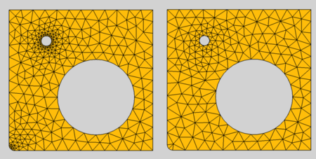
Effect of Mesh Size From Curvature; left: set to 12, right: deactivated
- ÚdajeOptimize Netgen: Whether the mesh will be optimized using the 3D mesh generator Netgen to improve the quality of tetrahedral elements. Note: since Netgen can only create tetrahedral elements, this option is ignored for meshes whose ÚdajeElement Dimension is not 3D.
- ÚdajeOptimize Std Optimizes the mesh to improve the quality of tetrahedral elements.
- ÚdajeRecombination Algorithm introduced in 0.20: The algorithm used for ÚdajeRecombine 3D All and also for ÚdajeRecombine All. For more info, see section Element Recombination and for technical details see the Gmsh documentation.
- ÚdajeRecombine 3D All introduced in 0.20: Applies a recombination 3D-algorithm to all volumes. Tetrahedra will be recombined into prisms, hexahedra or pyramids if possible.
- ÚdajeRecombine All: Applies a recombination algorithm to all surfaces. Triangles will be recombined into quadrangles when possible.
- ÚdajeSecond Order Linear: Option if second order nodes (if ÚdajeElement Order set to 2nd) and/or mesh refinement points are created by linear interpolation.
- true; linear interpolation is used
- false (default); curvilinear interpolation is used
- ÚdajeSubdivision Algorithm introduced in 1.0: allows the creation of quadrilateral and hexahedral elements by subdivision
- None; doesn't use any subdivision algorithm
- All Quadrangles; creates quadrilateral elements by subdivision
- All Hexahedra; creates hexahedral elements by subdivision
- Barycentric; creates triangular elements by barycentric subdivision
Notes
Nonpositive Jacobians
When you get a meshing error about nonpositive Jacobians, you can try out the following strategies:
- Set ÚdajeSecond Order Linear to true but keep ÚdajeElement Order at 2nd.
- Set ÚdajeElement Order to 1st.
- Use a smaller element size by reducing the ÚdajeCharacteristic Length Max.
- If solver ccxtools is used and the run button is used (not the task panel) the nodes of nonpositive jacobian elements will be green.
Mesh Growth
At edges and small geometric entities, the mesh has to be smaller than in areas without edges. So the mesh element size grows away from the edges. The growing strategy of Gmsh is to grow between edges of different sizes. So the growing fails when an area has the same sized edges like for example this tube:
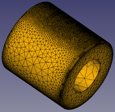
Failing mesh growing because the cylindrical area is surrounded by the same edges
To enable a sensible mesh growing, you must in this case add an edge to the area. In the example, this would be a circle in the middle of the cylinder. The circle is added as part of a BooleanFragments compound (to form a CompSolid), see the project file of the example.
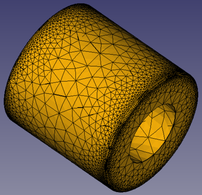
Sensible mesh growing due to the additional edge in the middle of the cylindrical area
Element Recombination
Elements can be recombined in two ways, on the surface of objects so that triangles will be recombined into quadrangles if possible and in the volume of objects so that tetrahedra will be recombined into prisms, hexahedra or pyramids if possible. Thinking about the geometry, it becomes clear that the recombination result depends strongly on the geometry of the body and that recombining a 3D body only at the surface will mostly lead to strange results.
To illustrate this, look at the image below. A cuboid body is meshed using the standard settings (tetrahedra, 2nd order mesh). This is the subimage at the upper left. The image at the upper right shows the result, when additionally the elements are recombined only at the surface of the body. The result is bad because the changed surface elements don't fit to the unchanged volume elements. So ÚdajeRecombine All alone usually only makes sense for 2D meshes.
When we use now also ÚdajeRecombine 3D All, the result is better, see the lower left subimage. However, the result doesn't show a great difference compared to the mesh without recombinations. Since our body is a cuboid, it is therefore sensible to use a recombination algorithm that tries to create cuboids as well. And this result is shown in the subimage at the lower right.
The Simple recombination algorithm will leave some triangles in the mesh in case the recombining leads to badly shaped quads. In such cases use a full-quad recombination algorithm, which will automatically perform a coarser mesh followed by the recombination, smoothing and subdividing. See forum topic
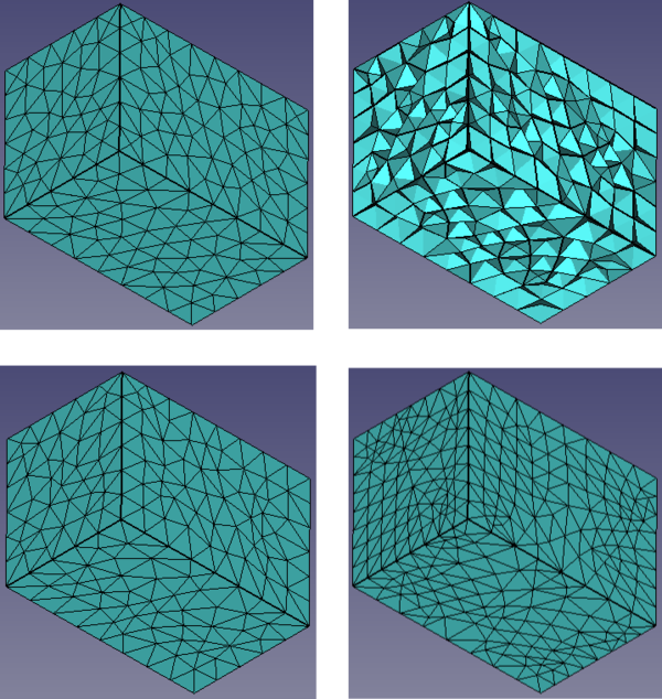
Effect of mesh element recombination.
Upper left: standard mesh.
Upper right: recombination only at the surface using the Simple algorithm.
Lower left: recombination at the surface and in the volume using the Simple algorithm.
Lower right: recombination at the surface and in the volume using the Simple full-quad algorithm
Tato stránka je načtena z https://wiki.freecad.org/FEM_MeshGmshFromShape