This documentation is not finished. Please help and contribute documentation.
GuiCommand model explains how commands should be documented. Browse Category:UnfinishedDocu to see more incomplete pages like this one. See Category:Command Reference for all commands.
See WikiPages to learn about editing the wiki pages, and go to Help FreeCAD to learn about other ways in which you can contribute.
|
|
| Menu location |
|---|
| Surfaces → Sketch on Surface |
| Workbenches |
| Curves |
| Default shortcut |
| None |
| Introduced in version |
| - |
| See also |
| None |
Descrizione
The ![]() Curves SketchOnSurface tool maps a sketch onto an arbitrary curved face, like a label on a bottle. The sketch must be actually attached to a face (see Sketch.Support). The
Curves SketchOnSurface tool maps a sketch onto an arbitrary curved face, like a label on a bottle. The sketch must be actually attached to a face (see Sketch.Support). The Map mode of the sketch has no effect on the result.
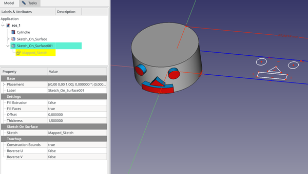
Above: shows the Sketch_On_Surface object applied to the cylinder face (left) and the source sketch in edit mode (right)
Utilizzo
There are 2 methods to use the SketchOnSurface tool:
Creating a sketch on a selected face
- Select the target face in the 3D view.
- There are several ways to invoke the tool:
- Press the
 Sketch on Surface button.
 - Select the Surfaces → Sketch on Surface option from the menu.
- Press the
- A Sketch_On_Surface object is created including a Mapped_Sketch object.
- Expand this object in the Tree view to make the Mapped_Sketch appear below.
- Edit the sketch and add geometries inside the blue construction bounds.
- Optionally edit the values in the Property editor to create extruded faces, or fill faces and equidistant faces from closed sketch wires, which in combination result in a solid shape, and adjust the related properties (see Properties below).
Attaching an existing sketch to a selected face
- Attach an existing sketch to the target face:
- Right-click on a sketch in the Tree view and select Attachment editor from the context menu.
- The Attachment dialog opens.
- Select the target face.
- Set the Attachment mode to Deactivated while keeping the face as the first reference.
- Press the OK button to close the Attachment dialog.
- In the Property editor set Placement.Position.z = 0.
- Edit the sketch and add a Construction (blue) rectangle around the geometries.
- This rectangle will be the parametric bounds of the face.
- Select the sketch.
- Invoke the tool as described above.
- A Sketch_On_Surface object is created including the selected sketch.
- Optionally edit the values in the Property editor as described above.
Notes
- The result is a 3D wire by default.
- To generate lofting faces from the sketch that are normal to the target face (the blue faces in the above screenshot) set the DatiFill Extrusion property to
trueand enter a value other than0.0for the DatiThickness property. - To close the lofted shape set the DatiFill Faces property to
true. - To only fill the 3D wire set the DatiFill Extrusion property to
false, the DatiFill Faces property totrue, and the DatiThickness property to0.0. Any other value for the latter will add a second equidistant face (the red faces in the above screenshot); Thickness is a distance value in this case). - to move the 3D wire above or below the target face enter a value other than
0.0for the DatiOffset property, this also moves any shape based on this wire accordingly. - It is assumed that all geometry in the sketch is enclosed within the blue construction frame. This includes all other construction geometry, as well as the visible internal geometry of complex curves (Bézier, Ellipse). If this is not the case the bounding box of the sketch will be larger than the construction frame and the final mapping will be scaled down accordingly. If required hide the internal geometry that is not fully inside the construction frame.
- If a sketch holds more construction geometry than only the necessary frame it is now recommended to not attach it directly, instead create a separate Mapped_Sketch object with the construction frame only, and link the desired sketch to the DatiExtra Objects property. (see: forum)
Properties
See also: Property editor.
A Sketch_On_Surface object is derived from a Part Feature object and inherits all its properties. It also has the following additional properties:
Data
Settings
- DatiFill Extrusion (
Bool): Add extrusion faces - DatiFill Faces (
Bool): Make faces from closed wires - DatiOffset (
Float): Offset distance of mapped sketch - DatiThickness (
Float): Extrusion thickness
SketchOnSurface
- DatiExtra Objects (
LinkList): Additional objects that will be mapped on surface - DatiSketch (
Link): Input Sketch
Touchup
- DatiConstruction Bounds (
Bool): include construction geometry in sketch bounds - DatiReverse U (
Bool): Reverse U direction - DatiReverse V (
Bool): Reverse V direction - DatiSwap UV (
Bool): Swap U and V directions
Questa pagina è recuperata da https://wiki.freecad.org/Curves_SketchOnSurface