- Introducción
- Descubriendo FreeCAD
- Trabajar con FreeCAD
- Guiones en Python
- La comunidad
En los capítulos anteriores, hemos aprendido sobre los diferentes ambientes de trabajo de FreeCAD, y cómo cada uno de ellos implementa sus propias herramientas y tipos de geometría. El mismo concepto se aplica cuando se trabaja desde el código de Python.
También vimos que la gran mayoría de los ambientes de trabajo de FreeCAD dependen de uno muy fundamental: el Ambiente de trabajo Pieza. De hecho, muchos otros ambientes de trabajo, como Borrador y Arquitectura, hacen exactamente lo que haremos en este capítulo: usar código Python para crear y manipular la geometría de la Pieza.
Así que lo primero que tenemos que hacer para trabajar con la geometría Pieza, es hacer el equivalente en Python a cambiar al Ambiente de trabajo Pieza: importar el módulo Pieza:
import Part
Tómese un momento para explorar el módulo Part escribiendo Part. en la consola de Python y revisar los métodos y atributos disponibles en la ventana de autocompletado. Esta es una excelente manera de familiarizarte con la funcionalidad que ofrece el módulo. Encontrará diversas funciones prácticas, como makeBox y makeCircle, que le permitan crear rápidamente formas y objetos geométricos con un solo comando. Muchas de estas funciones también ofrecen parámetros opcionales, lo que te brinda un control preciso sobre las dimensiones y la posición.
Dedicar cierto tiempo a explorar el contenido del módulo no solo le ayudará a comprender las herramientas que tiene a su disposición, sino que también le permitirá entender cómo funciona internamente el Entorno de trabajo de piezas. Este conocimiento fundamental le resultará decisivo a medida que avancemos y comencemos a crear y manipular geometría mediante programación. Escribe el siguiente comando.
Part.makeBox(3,5,7)
Este comando crea una caja 3D, también conocida como prisma rectangular, con dimensiones específicas. El primer parámetro, 3, define la longitud de la caja a lo largo del eje X. El segundo parámetro, 5, establece el ancho a lo largo del eje Y, y el tercer parámetro, 7, especifica la altura a lo largo del eje Z. Si bien esta función genera la geometría de la caja, no la agrega automáticamente al documento FreeCAD activo. En la consola de Python verá lo siguiente:
<Solid object at 0x5f43600>
El mensaje <Objeto sólido en 0x5f43600> indica que se ha creado una forma de pieza en la memoria. Se trata de un objeto geométrico almacenado en una dirección de memoria específica, como lo muestra el valor hexadecimal (0x5f43600). Sin embargo, es importante tener en cuenta que lo que hemos creado aún no es un objeto de documento de FreeCAD; existe únicamente como una forma geométrica básica en la memoria.
Esta distinción destaca un concepto fundamental en FreeCAD: los objetos y su geometría son independientes. Un objeto de documento de FreeCAD actúa como un contenedor que alberga una forma. Estos objetos pueden tener propiedades adicionales, como longitud, anchura y altura, y pueden ser paramétricos. Los objetos paramétricos recalculan su geometría (o forma) dinámicamente cada vez que cambia alguna de sus propiedades. Por ejemplo, al modificar la longitud de una caja paramétrica, su forma se reconstruirá automáticamente con el valor actualizado.
En este caso, creamos manualmente una forma usando la función Part.makeBox(). Esta forma es un objeto no paramétrico, lo que significa que no se actualiza automáticamente según ninguna propiedad; es estática a menos que la manipulemos mediante programación. Para que esta forma forme parte del documento FreeCAD activo, sería necesario asignarla a un objeto de documento (como Part::Feature), lo que la vincularía a la interfaz gráfica y la haría visible y manejable dentro del entorno FreeCAD.
Observe como manejamos miObj.Shape , note que se hace exactamente como lo hicimos en el capítulo anterior, cuando cambiamos otras propiedades de un objeto, como box.Height = 5 . De hecho, Forma también es una propiedad, al igual que Altura'. Sólo que toma una Forma Pieza, no un número. En el próximo capítulo veremos mejor cómo se construyen estos objetos paramétricos.
Ahora podemos crear fácilmente un objeto de documento "genérico" en el documento actual (asegúrese de tener al menos un documento nuevo abierto) y darle una forma de caja como la que acabamos de crear:
boxShape = Part.makeBox(3,5,7)
myObj = FreeCAD.ActiveDocument.addObject("Part::Feature","MyNewBox")
myObj.Shape = boxShape
FreeCAD.ActiveDocument.recompute()
Aquí tenéis un desglose de los comandos anteriores:
- boxShape = Part.makeBox(3,5,7)': Crea una caja 3D con dimensiones 3x5x7 (largo, ancho y alto) y la almacena como una forma de pieza en la variable boxShape. Esta forma existe solo en la memoria y aún no forma parte del documento de FreeCAD.
- myObj = FreeCAD.ActiveDocument.addObject("Part::Feature", "MyNewBox"): Agrega un nuevo objeto Part::Feature llamado "MyNewBox" al documento FreeCAD activo y lo asigna a la variable myObj. El nuevo objeto aparecerá en el árbol del documento FreeCAD.
- myObj.Shape = boxShape: Vincula la geometría boxShape con la propiedad Shape de myObj, integrando la geometría en el documento de FreeCAD.
- FreeCAD.ActiveDocument.recompute(): Actualiza el documento para reflejar los cambios, asegurando que el nuevo objeto y su geometría aparezcan en la interfaz gráfica.
Observe cómo manejamos myObj.Shape. Se hizo de la misma manera que en el capítulo anterior, donde modificamos otras propiedades de un objeto, como box.Height = 5. De hecho, Shape también es una propiedad, al igual que Height. Sin embargo, en lugar de aceptar un número, Shape requiere una característica de la forma. En el próximo capítulo, analizaremos con más detalle cómo se construyen estos objetos paramétricos.
Por ahora, exploremos las formas de las piezas con más detalle. En el capítulo sobre modelado tradicional con el Entorno de trabajo de piezas, presentamos una tabla que explica cómo se construyen las formas de las piezas y los diferentes componentes que las conforman, como vértices, aristas y caras. Estos mismos componentes están disponibles al trabajar con las formas de las piezas en Python, lo que permite una exploración y manipulación detallada de la geometría. Las formas de las piezas en FreeCAD siempre tienen los siguientes atributos:
- Vértices: Puntos en el espacio 3D que definen las esquinas o los extremos de una geometría.
- Aristas: Líneas rectas o curvas que conectan dos vértices.
- Cables: Bucles cerrados o abiertos formados por una o más aristas conectadas.
- Caras: Superficies delimitadas por uno o más cables.
- Cáscaras: Grupos de caras conectadas que forman una superficie continua.
- Sólidos: Volúmenes 3D delimitados por una o más cáscaras.
En Python, todos estos atributos se representan como listas. Cada lista puede contener cualquier número de elementos o estar vacía, dependiendo de la forma que se esté analizando. Por ejemplo, una caja tendrá ocho Vértices, doce Aristas, seis Caras, una Cáscara y un Sólido, mientras que una línea solo tendrá dos Vértices y una Arista, estando todos los demás atributos vacíos. Estos componentes son bloques de construcción fundamentales de la geometría de las piezas y se puede acceder a ellos y manipularlos mediante programación. Comprender cómo interactúan proporciona un poderoso control sobre la creación y modificación de modelos 3D. Podemos acceder a esas listas de la siguiente manera:
print(boxShape.Vertexes)
print(boxShape.Edges)
print(boxShape.Wires)
print(boxShape.Faces)
print(boxShape.Shells)
print(boxShape.Solids)
Calculemos el área de cada cara de la figura cuadrada que se muestra arriba: (Asegúrese de aplicar sangría a la segunda línea, tal como aparece a continuación. Presione Enter dos veces después de la última línea para ejecutar el comando de Python).
for f in boxShape.Faces:
   print(f.Area)
O bien, para cada arista, su punto de inicio y su punto final:
for e in boxShape.Edges:
   print("New edge")
   print("Start point:")
   print(e.Vertexes[0].Point)
   print("End point:")
   print(e.Vertexes[1].Point)
Como ves, si nuestra boxShape tiene un atributo "Vértices", cada arista de la boxShape también tiene un atributo "Vértices". Como podemos esperar, la boxShape tendrá 8 vértices, mientras que la arista sólo tendrá 2, que son ambos parte de la lista de 8.
Siempre podemos comprobar cuál es el tipo de una forma:
print(boxShape.ShapeType)
print(boxShape.Faces[0].ShapeType)
print(boxShape.Vertexes[2].ShapeType)
A continuación, una breve explicación de los comandos anteriores: *print(boxShape.ShapeType): Muestra el tipo de la forma de nivel superior representada por boxShape. En este caso, dado que boxShape se creó como una caja usando Part.makeBox, el resultado será "Solid", lo que indica que la forma es un objeto sólido 3D.
- print(boxShape.Faces[0].ShapeType): Accede a la primera cara en la lista Faces de boxShape (índice 0) e imprime su tipo de forma. Para una caja, cada cara es una superficie plana, por lo que la salida será "Face".
- print(boxShape.Vertexes[2].ShapeType): Accede al tercer vértice en la lista Vertexes de boxShape (índice 2) e imprime su tipo de forma. Dado que se trata de un punto específico en el espacio 3D, la salida será "Vertex".
Para resumir el concepto de Partes de la Forma: Todo comienza con los Vértices, los elementos más básicos de la geometría. Usando uno o dos Vértices, puedes crear una Arista (ten en cuenta que los círculos completos solo requieren un Vértice). Una o más Aristas pueden formar un cable, que puede ser abierto o cerrado. Cuando tienes uno o más cables cerrados, puedes crear una Cara. Los cables adicionales dentro del cable principal actuarán como "agujeros" en la Cara. Combinando una o más Caras puedes construir una Cáscara, que es esencialmente una colección de superficies conectadas. Si una Cáscara está completamente cerrada y es impermeable, se puede usar para formar un Sólido, un objeto 3D con volumen. Finalmente, cualquier número de formas de cualquier tipo, incluyendo Vértices, Aristas, Alámbricos, Caras, Cáscaras o Sólidos, se pueden agrupar en un Compuesto, que actúa como un contenedor para múltiples formas.
Ahora podemos intentar crear formas complejas desde cero, construyendo todos sus componentes uno a uno. Por ejemplo, intentemos crear un volumen como éste:
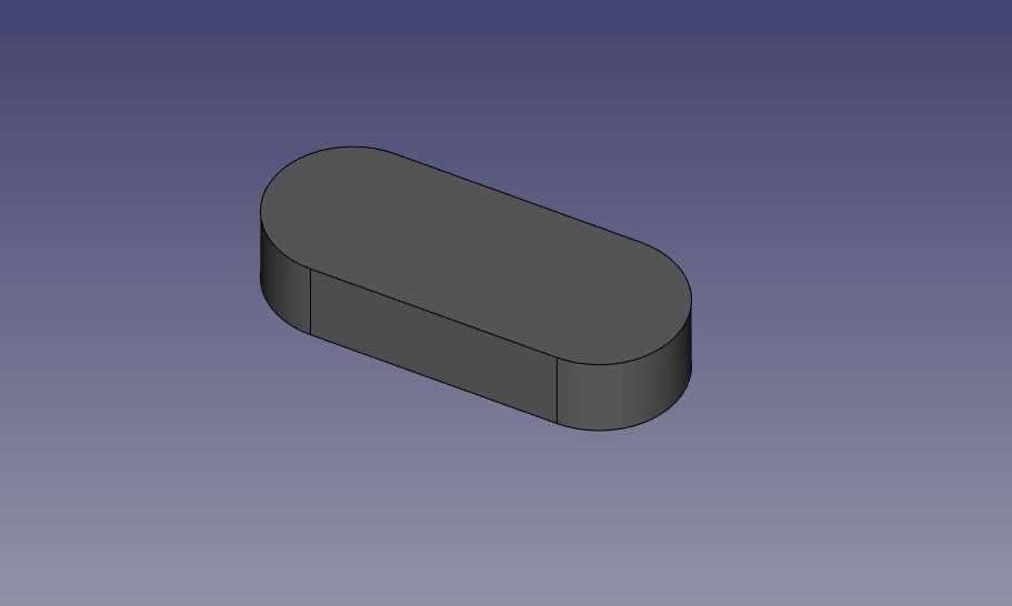
Empezaremos creando una forma plana como ésta:
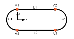
En primer lugar, vamos a crear los cuatro puntos base:
V1 = FreeCAD.Vector(0,10,0)
V2 = FreeCAD.Vector(30,10,0)
V3 = FreeCAD.Vector(30,-10,0)
V4 = FreeCAD.Vector(0,-10,0)
Entonces podemos crear los dos segmentos lineales:
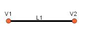
L1 = Part.LineSegment(V1,V2)
L2 = Part.LineSegment(V4,V3)
Tenga en cuenta que no necesitamos crear Vértices explícitamente. En su lugar, podríamos crear directamente Part.LineSegments usando FreeCAD Vectors. Esto se debe a que en esta etapa estamos trabajando con geometría base, no con Aristas reales. Un Part.LineSegment, así como Part.Circle, Part.Arc, Part.Ellipse o Part.BSpline, define la geometría subyacente pero no genera una arista por sí mismo. En FreeCAD, las aristas siempre se construyen a partir de dicha geometría base, que se almacena en el atributo Curve de Edge. Esto significa que una arista es esencialmente un contenedor alrededor de la geometría base, heredando sus propiedades. Si tiene una arista, puede acceder a su geometría subyacente haciendo referencia al atributo curve. El siguiente comando:
print(Edge.Curve)
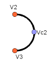
Esto permite comprender la estructura subyacente del borde y cómo se construyó. Ahora, volvamos a nuestro ejercicio y procedamos a construir los segmentos del arco. Para crear un arco, necesitamos tres puntos: un punto de inicio, un punto final y un punto medio que determine el radio de curvatura. Para ello, podemos usar la eficaz función Part.Arc, que toma estos tres puntos como entrada y genera la geometría base del arco.
VC1 = FreeCAD.Vector(-10,0,0)
C1 = Part.Arc(V1,VC1,V4)
VC2 = FreeCAD.Vector(40,0,0)
C2 = Part.Arc(V2,VC2,V3)
Ahora tenemos 2 líneas (L1 y L2) y 2 arcos (C1 y C2). Tenemos que convertirlos en aristas:
E1 = Part.Edge(L1)
E2 = Part.Edge(L2)
E3 = Part.Edge(C1)
E4 = Part.Edge(C2)
Alternativamente, las geometrías base también tienen una función toShape() que hace exactamente lo mismo:
E1 = L1.toShape()
E2 = L2.toShape()
 ...
Una vez que tenemos una serie de Aristas, ahora podemos formar un Hilo, dándole una lista de Aristas. Debemos tener en cuenta el orden.
W = Part.Wire([E1,E4,E2,E3])
Y podemos comprobar si nuestro hilo se ha entendido correctamente, y que está correctamente cerrado:
print( W.isClosed() )
Que imprimirá "Verdadero" o "Falso". Para hacer una Cara, necesitamos Hilos cerrados, por lo que siempre es una buena idea comprobarlo antes de crear la Cara. Ahora podemos crear una Cara, dándole un solo Alambre (o una lista de Alambres si queremos agujeros):
F = Part.Face(W)
Entonces lo extruimos:
P = F.extrude(FreeCAD.Vector(0,0,10))
Tenga en cuenta que P ya es un sólido:
print(P.ShapeType)
Esto se debe a que cuando extruimos una sola Cara, siempre obtenemos un Sólido. Este no sería el caso, por ejemplo, si hubiéramos extruido el Hilo en su lugar:
S = W.extrude(FreeCAD.Vector(0,0,10))
print(S.ShapeType)
Lo que, por supuesto, nos dará una carcasa hueca, a la que le faltan las caras superior e inferior.
Ahora que tenemos nuestra forma final, estamos ansiosos por verla en pantalla. Así que vamos a crear un objeto genérico, y asignarle nuestro nuevo Sólido:
myObj2 = FreeCAD.ActiveDocument.addObject("Part::Feature","My_Strange_Solid")
myObj2.Shape = P
FreeCAD.ActiveDocument.recompute()
Como alternativa, el módulo Pieza también proporciona un acceso directo que realiza la operación anterior más rápidamente (pero no se puede elegir el nombre del objeto):
Part.show(P)
Todo lo anterior, y mucho más, se explica en detalle en la página Guionización Pieza, junto con ejemplos.
Leer más
Esta página ha sido recuperada de https://wiki.freecad.org/Manual:Creating_and_manipulating_geometry