Introduction
The graphical user interface workflow for the Drawing Workbench is limited, so the scripting API is more interesting.
Simple example
First of all you need the Part and the Drawing module:
import FreeCAD, Part, Drawing
Create a small sample part
Part.show(Part.makeBox(100,100,100).cut(Part.makeCylinder(80,100)).cut(Part.makeBox(90,40,100)).cut(Part.makeBox(20,85,100)))
Direct projection. The G0 means hard edge, the G1 is tangent continuous.
Shape = App.ActiveDocument.Shape.Shape
[visibleG0,visibleG1,hiddenG0,hiddenG1] = Drawing.project(Shape)
print "visible edges:", len(visibleG0.Edges)
print "hidden edges:", len(hiddenG0.Edges)
Everything was projected on the Z-plane:
print "Bnd Box shape: X=",Shape.BoundBox.XLength," Y=",Shape.BoundBox.YLength," Z=",Shape.BoundBox.ZLength
print "Bnd Box project: X=",visibleG0.BoundBox.XLength," Y=",visibleG0.BoundBox.YLength," Z=",visibleG0.BoundBox.ZLength
Different projection vector
[visibleG0,visibleG1,hiddenG0,hiddenG1] = Drawing.project(Shape,App.Vector(1,1,1))
Project to SVG
resultSVG = Drawing.projectToSVG(Shape,App.Vector(1,1,1))
print resultSVG
Parametric example
Create the body
import FreeCAD
import Part
import Drawing

# Create three boxes and a cylinder
App.ActiveDocument.addObject("Part::Box","Box")
App.ActiveDocument.Box.Length=100.00
App.ActiveDocument.Box.Width=100.00
App.ActiveDocument.Box.Height=100.00

App.ActiveDocument.addObject("Part::Box","Box1")
App.ActiveDocument.Box1.Length=90.00
App.ActiveDocument.Box1.Width=40.00
App.ActiveDocument.Box1.Height=100.00

App.ActiveDocument.addObject("Part::Box","Box2")
App.ActiveDocument.Box2.Length=20.00
App.ActiveDocument.Box2.Width=85.00
App.ActiveDocument.Box2.Height=100.00

App.ActiveDocument.addObject("Part::Cylinder","Cylinder")
App.ActiveDocument.Cylinder.Radius=80.00
App.ActiveDocument.Cylinder.Height=100.00
App.ActiveDocument.Cylinder.Angle=360.00
# Fuse two boxes and the cylinder
App.ActiveDocument.addObject("Part::Fuse","Fusion")
App.ActiveDocument.Fusion.Base = App.ActiveDocument.Cylinder
App.ActiveDocument.Fusion.Tool = App.ActiveDocument.Box1

App.ActiveDocument.addObject("Part::Fuse","Fusion1")
App.ActiveDocument.Fusion1.Base = App.ActiveDocument.Box2
App.ActiveDocument.Fusion1.Tool = App.ActiveDocument.Fusion
# Cut the fused shapes from the first box
App.ActiveDocument.addObject("Part::Cut","Shape")
App.ActiveDocument.Shape.Base = App.ActiveDocument.Box
App.ActiveDocument.Shape.Tool = App.ActiveDocument.Fusion1
# Hide all the intermediate shapes
Gui.ActiveDocument.Box.Visibility=False
Gui.ActiveDocument.Box1.Visibility=False
Gui.ActiveDocument.Box2.Visibility=False
Gui.ActiveDocument.Cylinder.Visibility=False
Gui.ActiveDocument.Fusion.Visibility=False
Gui.ActiveDocument.Fusion1.Visibility=False
Insert a Page object and assign a template
App.ActiveDocument.addObject('Drawing::FeaturePage','Page')
App.ActiveDocument.Page.Template = App.getResourceDir()+'Mod/Drawing/Templates/A3_Landscape.svg'
Create a view on the "Shape" object, define the position and scale and assign it to a Page
App.ActiveDocument.addObject('Drawing::FeatureViewPart','View')
App.ActiveDocument.View.Source = App.ActiveDocument.Shape
App.ActiveDocument.View.Direction = (0.0,0.0,1.0)
App.ActiveDocument.View.X = 10.0
App.ActiveDocument.View.Y = 10.0
App.ActiveDocument.Page.addObject(App.ActiveDocument.View)
Create a second view on the same object but this time the view will be rotated by 90 degrees.
App.ActiveDocument.addObject('Drawing::FeatureViewPart','ViewRot')
App.ActiveDocument.ViewRot.Source = App.ActiveDocument.Shape
App.ActiveDocument.ViewRot.Direction = (0.0,0.0,1.0)
App.ActiveDocument.ViewRot.X = 290.0
App.ActiveDocument.ViewRot.Y = 30.0
App.ActiveDocument.ViewRot.Scale = 1.0
App.ActiveDocument.ViewRot.Rotation = 90.0
App.ActiveDocument.Page.addObject(App.ActiveDocument.ViewRot)
Create a third view on the same object but with an isometric view direction. The hidden lines are activated too.
App.ActiveDocument.addObject('Drawing::FeatureViewPart','ViewIso')
App.ActiveDocument.ViewIso.Source = App.ActiveDocument.Shape
App.ActiveDocument.ViewIso.Direction = (1.0,1.0,1.0)
App.ActiveDocument.ViewIso.X = 335.0
App.ActiveDocument.ViewIso.Y = 140.0
App.ActiveDocument.ViewIso.ShowHiddenLines = True
App.ActiveDocument.Page.addObject(App.ActiveDocument.ViewIso)
Change something and update. The update process changes the view and the page.
App.ActiveDocument.View.X = 30.0
App.ActiveDocument.View.Y = 30.0
App.ActiveDocument.View.Scale = 1.5
App.ActiveDocument.recompute()
Accessing the bits and pieces
Get the SVG fragment of a single view
ViewSVG = App.ActiveDocument.View.ViewResult
print ViewSVG
Get the whole result page (it's a file in the document's temporary directory, only read permission)
print "Resulting SVG document: ",App.ActiveDocument.Page.PageResult
file = open(App.ActiveDocument.Page.PageResult,"r")
print "Result page is ",len(file.readlines())," lines long"
Important: free the file!
del file
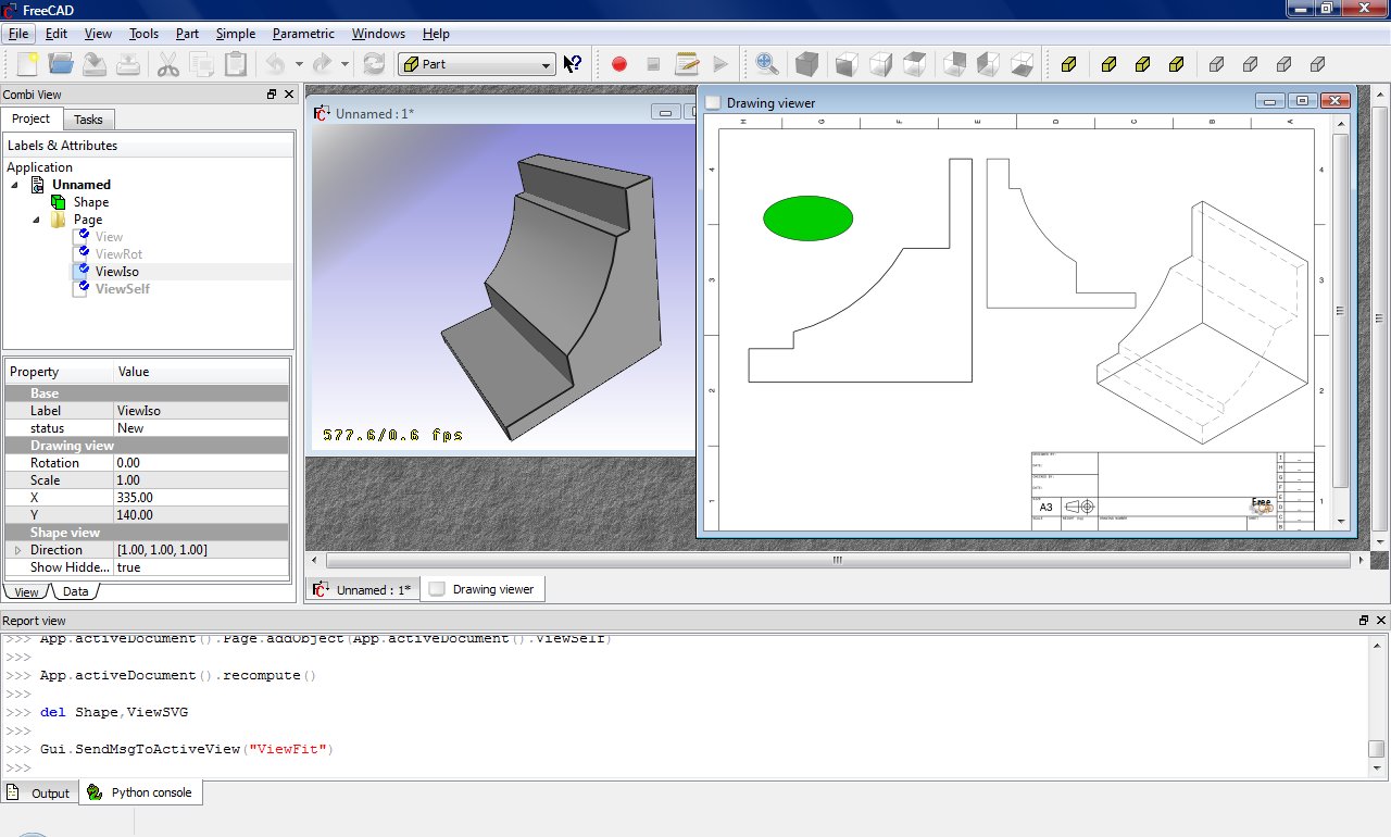
Insert a view with your own content:
App.ActiveDocument.addObject('Drawing::FeatureView','ViewSelf')
App.ActiveDocument.ViewSelf.ViewResult = """<g id="ViewSelf"
  stroke="rgb(0, 0, 0)"
  stroke-width="0.35"
  stroke-linecap="butt"
  stroke-linejoin="miter"
  transform="translate(30,30)"
  fill="#00cc00"
  >

  <ellipse cx="40" cy="40" rx="30" ry="15"/>
  </g>"""
App.ActiveDocument.Page.addObject(App.ActiveDocument.ViewSelf)
App.ActiveDocument.recompute()

del ViewSVG
That leads to the following result:
General dimensioning and tolerancing
See also: Drawing Dimensioning Addon
Drawing dimensions an tolerances are still under development but you can get some basic functionality with a bit of work.
First you need to get the gdtsvg python module from here (WARNING: This could be broken at any time!):
https://github.com/jcc242/FreeCAD
To get a feature control frame, try out the following:
import gdtsvg as g # Import the module, I like to give it an easy handle
ourFrame = g.ControlFrame("0","0", g.Perpendicularity(), ".5", g.Diameter(), g.ModifyingSymbols("M"), "A",
           g.ModifyingSymbols("F"), "B", g.ModifyingSymbols("L"), "C", g.ModifyingSymbols("I"))
Here is a good breakdown of the contents of a feature control frame: http://www.cadblog.net/adding-geometric-tolerances.htm
The parameters to pass to control frame are:
- X-coordinate in SVG-coordinate system (type string)
- Y-coordinate in SVG-coordinate system (type string)
- The desired geometric characteristic symbol (tuple, svg string as first, width of symbol as second, height of symbol as third)
- The tolerance (type string)
- (optional) The diameter symbol (tuple, svg string as first, width of symbol as second, height of symbol as third)
- (optional) The condition modifying material (tuple, svg string as first, width of symbol as second, height of symbol as third)
- (optional) The first datum (type string)
- (optional) The first datum's modifying condition (tuple, svg string as first, width of symbol as second, height of symbol as third)
- (optional) The second datum (type string)
- (optional) The second datum's modifying condition (tuple, svg string as first, width of symbol as second, height of symbol as third)
- (optional) The third datum (type string)
- (optional) The third datum's material condition (tuple, svg string as first, width of symbol as second, height of symbol as third)
The ControlFrame function returns a type containing (svg string, overall width of control frame, overall height of control frame)
To get a dimension, try out the following:
import gdtsvg
ourDimension = linearDimension(point1, point2, textpoint, dimensiontext, linestyle=getStyle("visible"),
               arrowstyle=getStyle("filled"), textstyle=getStyle("text")
Inputs for linear dimension are:
- point1, an (x,y) tuple with svg-coordinates, this is one of the points you would like to dimension between
- point2, an (x,y) tuple with svg-coordinates, this is the second point you would like to dimension between
- textpoint, an (x,y) tuple of svg-coordinates, this is where the text of your dimension will be
- dimensiontext, a string containing the text you want the dimension to say
- linestyle, a string containing svg (i.e. css) styles, using the getStyle function to retrieve a preset string, for styling the how the lines look
- arrowstyle, a string containing svg (i.e. css) styles, using the getStyle function to retrieve a preset string, for styling how the arrows look
- textstyle, a string containing svg (i.e. css) styles, using the getStyle function to retrieve a preset string, for styling how the text looks
With those two, you can proceed as above for displaying them on the drawing page. This module is very buggy and can be broken at any given moment, bug reports are welcome on the github page for now, or contact jcc242 on the forums if you post a bug somewhere else.
This page is retrieved from https://wiki.freecad.org/Drawing_API_example