Úvod
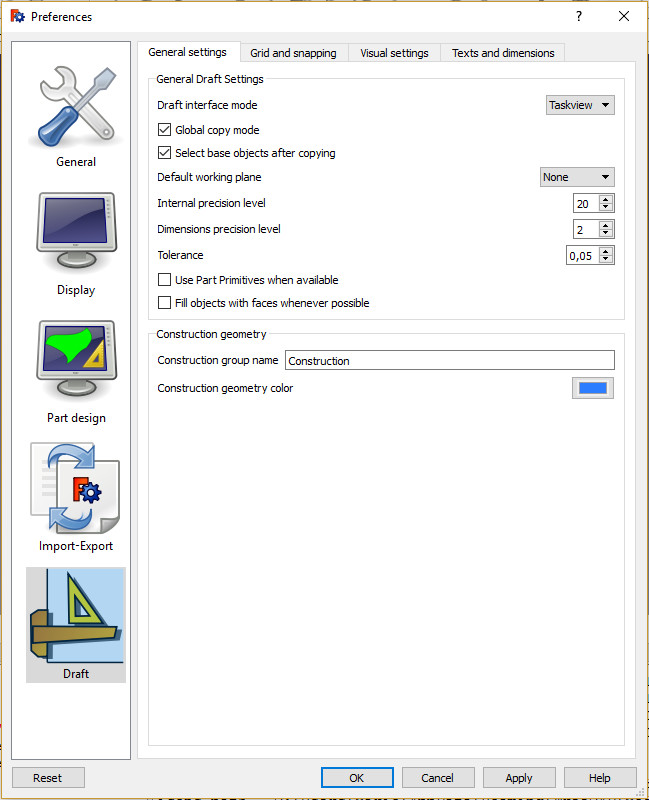
The preferences for the ![]() Draft Workbench can be found in the Preferences Editor. In the menu select Edit → Preferences and then
Draft Workbench can be found in the Preferences Editor. In the menu select Edit → Preferences and then ![]() Draft. This group is only available if the Draft Workbench has been loaded in the current FreeCAD session.
Draft. This group is only available if the Draft Workbench has been loaded in the current FreeCAD session.
There are five pages: General, Interface, Grid and Snapping, Visual and Texts and Dimensions.
Some advanced preferences can only be changed in the Parameter Editor. See Fine-tuning.
This page has been updated for version 1.1.
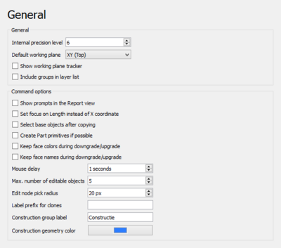
On this page you can specify the following:
| Name | Description |
|---|---|
| Internal precision level | The number of decimals used in internal coordinate operations (for example 3 = 0.001). Values between 6 and 8 are usually considered the best trade-off. |
| Default working plane | The default working plane for new views. The options are:
|
| Show working plane orientation | If checked, a widget indicating the current working plane orientation appears when picking points. |
| Include groups in layer list | If checked, the layers drop-down list also includes groups. Objects can then automatically be added to groups as well. See Draft AutoGroup. |
| Show prompts in the Report View | If checked, instructions are displayed in the Report View when using Draft commands. introduced in 1.0 |
| Set focus on Length instead of X coordinate | If checked, Length input, instead of the X coordinate, will have the initial focus. This allows to indicate a direction and then type a distance. |
| Select base objects after copying | If checked, base objects, instead of created copies, are selected after copying. |
| Create Part primitives if possible | If checked, Draft commands will create Part primitives instead of Draft objects. Note that this is not fully supported, and many objects will not be editable with Draft modification commands. |
| Keep face colors during downgrade/upgrade | If checked, Draft Downgrade and Draft Upgrade will keep face colors. Only for the splitFaces and makeShell options. |
| Keep face names during downgrade/upgrade | If checked, Draft Downgrade and Draft Upgrade will keep face names. Only for the splitFaces and makeShell options. |
| Mouse delay | This is the delay in seconds during which the mouse is inactive after entering a number in one of the Draft task panel input fields. During the delay moving the mouse won't change the entered value. Set to 0 to disable the delay. |
| Max. number of editable objects | The maximum number of objects Draft Edit is allowed to process at the same time. |
| Edit node pick radius | The pick radius of edit nodes. |
| Label prefix for clones | The default prefix added to the label of new clones. |
| Construction group label | The default label for the construction geometry group. |
| Construction geometry color | The default color for Draft objects in construction mode. |
Interface
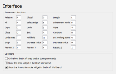
On this page you can specify the following:
| Name | Description |
|---|---|
| In-Command Shortcuts | These shortcuts only work when a Draft or BIM command is active. Note that not all commands support all shortcuts. |
| Relative | Shortcut to toggle relative mode. If relative mode is on, coordinates are relative to the last point, if available, else they are relative to the coordinate system origin. |
| Global | Shortcut to toggle global mode. If global mode is on, coordinates are relative to the global coordinate system, else they are relative to the working plane coordinate system. |
| Length | Shortcut to change the focus from the X coordinate input box to the Length input box and vice versa. |
| Make face | Shortcut to toggle filled mode. If filled mode is on, the created object will have ÚdajeMake Face set to true.
|
| Select edge | Shortcut to press the Select Edge button. See Draft Dimension. |
| Subelement mode | Shortcut to toggle subelement mode. If subelement mode is on, the command will use the selected subelements instead of the whole objects. |
| Copy | Shortcut to toggle copy mode. If copy mode is on, the command will create modified copies instead of modifying the original objects. |
| Undo | Shortcut to press the Undo button. |
| Wipe | Shortcut to press the Wipe button. |
| Close | Shortcut to press the Close button. |
| Exit | Shortcut to press the Finish button. |
| Continue | Shortcut to toggle continue mode. If continue mode is on, commands will restart after finishing. |
| Cycle snap | Shortcut to change snap priority to an object that is obscured by other geometry. See Draft Snap. |
| Add hold | Shortcut to insert a "hold point" at the current location of the cursor. See Draft Snap. |
| Set working plane | Shortcut to press the Set Working Plane button. |
| Snap | Shortcut to toggle Draft snapping. |
| Increase radius | Shortcut to increase the maximum distance at which Draft Snap Grid detects the intersections of grid lines. See Draft SelectPlane. |
| Decrease radius | Shortcut to decrease the maximum distance at which Draft Snap Grid detects the intersections of grid lines. |
| Restrict X | Shortcut to constrain the movement of the cursor to the X axis. See Draft Constrain. |
| Restrict Y | Shortcut to constrain the movement of the cursor to the Y axis. |
| Restrict Z | Shortcut to constrain the movement of the cursor to the Z axis. |
| Recenter | Shortcut to temporarily recenter the working plane during commands. See Draft Snap. introduced in 1.1 |
| Only show the Draft Snap toolbar during commands | If checked, the Draft Snap toolbar will only be visible during commands. introduced in 1.0 |
| Show the Draft Snap Widget in the Draft Workbench | If checked, the Draft Snap Widget is displayed in the Draft Status Bar. |
| Show the Draft Scale Widget in the Draft Workbench | If checked, the Draft Scale Widget is displayed in the Draft Status Bar. |
Grid and Snapping
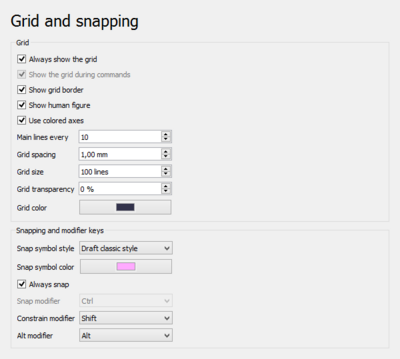
Note that several grid preferences can also be changed with the Draft SelectPlane command.
On this page you can specify the following:
| Name | Description |
|---|---|
| Always show the grid | If checked, the grid will always be visible in new views. Use Draft ToggleGrid to change this for the active view. |
| Show the grid during commands | If checked, the grid will be visible during commands in new views. Use Draft ToggleGrid to change this for the active view. introduced in 1.0 |
| Show grid border | If checked, an additional border is displayed around the grid, showing the main square size in the bottom left corner. |
| Show human figure | If checked, the outline of a human figure is displayed at the bottom left corner of the grid. Only effective if Show grid border is enabled. |
| Use colored axes | If checked, the two main axes of the grid are colored red, green or blue if they match the X, Y or Z axis of the global coordinate system. |
| Major lines every | The number of squares between major grid lines. Major grid lines are thicker than minor grid lines. |
| Grid spacing | The distance between grid lines. |
| Grid size | The number of squares in the X and Y direction of the grid. |
| Grid transparency | The overall transparency of the grid. |
| Grid color | The color of the grid. |
| Snap symbol style | The style for snap symbols. The options are:
|
| Snap symbol color | The color for snap symbols, snap dimensions and edit nodes. |
| Always snap | If checked, snapping is activated without the need to press the Snap modifier key. |
| Snap modifier | The Snap modifier key. |
| Constrain modifier | The Constrain modifier key. |
| Alt modifier | The Alt modifier key. The function of this key depends on the command. |
Visual
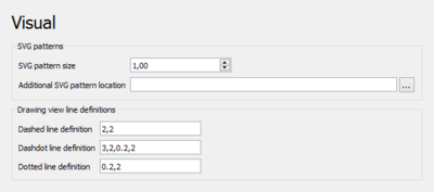
On this page you can specify the following:
| Name | Description |
|---|---|
| SVG pattern size | The default size for SVG patterns. A higher value results in a denser pattern.
|
| Additional SVG pattern location | An optional directory with custom SVG files containing pattern definitions to be added to the standard patterns. |
| Dashed line definition | An SVG linestyle definition used by the TechDraw DraftView command. |
| Dashdot line definition | Idem. |
| Dotted line definition | Idem. |
Texts and Dimensions

These preferences are the defaults used when creating new objects. Changing them does not affect existing objects.
On this page you can specify the following:
| Name | Description |
|---|---|
| Scale multiplier | The default annotation scale multiplier. This is the inverse of the scale set in the Draft Scale Widget. If the scale is 1:100 the multiplier is 100. introduced in 1.0
|
| Font name | The default font for texts, dimensions and labels. introduced in 1.1 |
| Font size | The default height for texts, dimension texts and label texts. |
| Line spacing factor | The default line spacing for multi-line texts and labels (relative to the font size). |
| Text color | The default color for texts, dimension texts and label texts. |
| Show dimension line | If checked, the dimension line is displayed by default. |
| Line width | The default line width. |
| Start arrow type | The default symbol displayed at the start of dimension lines. The options are:
|
| Start arrows size | The default size for start arrows. introduced in 1.1 |
| End arrow type | The default symbol displayed at the end of dimension lines. See Start arrow type. introduced in 1.1 |
| End arrows size | The default size for end arrows. introduced in 1.1 |
| Line and arrow color | The default color for lines and arrows. |
| Show unit | If checked, a unit symbol is added to dimension texts by default. |
| Unit override | The default unit override for dimensions. Enter a unit such as m or cm, leave blank to use the current unit defined in FreeCAD.
|
| Number of decimals | The default number of decimal places for dimension texts. |
| Feet separator | The optional string inserted between the feet and inches values in dimensions. introduced in 1.0 |
| Dimension line overshoot | The default distance the dimension line is extended past the extension lines. |
| Extension line length | The default length of extension lines. Use 0 for full extension lines. A negative value defines the gap between the ends of the extension lines and the measured points. A positive value defines the maximum length of the extension lines. Only used for linear dimensions.
|
| Extension line overshoot | The default length of extension lines above the dimension line. |
| Text spacing | The default space between the dimension line and the dimension text. |
Tato stránka je načtena z https://wiki.freecad.org/Draft_Preferences