GuiCommand: Name: Std LinkMake MenuLocation: None Workbenches: All Version: 0.19 SeeAlso: Std_Part, Std_Group, PartDesign_Body
Std LinkMake
Description
creates an App Link (App::Link class), a type of object that references or links to another object in the same document, or in another document. It is especially designed to efficiently duplicate a single object multiple times, which helps with the creation of complex assemblies from smaller subassemblies, and from multiple reusable components like screws, nuts, and similar fasteners.
The App Link object was newly introduced in v0.19; in the past, simple duplication of objects could be achieved with [ Draft Clone, but this is a less efficient solution due to its implementation, which essentially creates a copy of the internal Shape of the source object. Instead, a Link directly references the original Shape, so it is more memory-efficient.
By itself the Link object can behave like an array, duplicating its base object many times; this can be done by setting its Element Count property to {{Value|1}} or larger. This \"Link Array\" object can also be created with the different array tools of the  Draft Workbench, for example, [
 Draft OrthoArray, [
 Draft PolarArray, and [
 Draft CircularArray.
When used with the  PartDesign Workbench, Links are intended to be used with [
 PartDesign Bodies, so it is recommended to set Display Mode Body to {{Value|Tip}} to select the features of the entire Body, and not the individual features. To create arrays of the internal PartDesign Features, use [
 PartDesign LinearPattern, [
 PartDesign PolarPattern, and [
![]() PartDesign MultiTransform.
PartDesign MultiTransform.
The [ Std LinkMake tool is not defined by a particular workbench, but by the base system, thus it is found in the structure toolbar that is available in all workbenches. The Link object, used in conjunction with [
 Std Part to group various objects, forms the basis of the
 ![]() Assembly3 and
Assembly3 and ![]() Assembly4 Workbenches.
Assembly4 Workbenches.
Usage
With selection:
- Select an object in the tree view or 3D view for which you wish to create a Link.
- Press the [ Make link button. The produced object has the same icon as the original object, but has an arrow overlay indicating it is a Link.
Without selection:
- If no object is selected, press the [ Make link button to create an empty
 Link.
Link. - Go to the property editor, then click on the Linked Object property to open the Link selection dialog to choose an object, then press OK.
- Instead of choosing an entire object in the tree view, you can also pick subelements (vertices, edges, or faces) of a single object in the 3D view. In this case, the Link will duplicate only these subelements, and the arrow overlay will be different. This can also be done with [
 Std LinkMakeRelative.


(1) An object, (2) an empty Link, (3) a full Link to the first object (with overriding material), and (4) a Link to only some subelements of the object. The empty Link is not tied to the real object so it is not displayed in the 3D view.
Usage: external documents
- Start with a document that has at least one object which will be the source of the Link.
- Open a new document or an existing document. For easier handling, use [
 Std TreeMultiDocument to show both documents in the tree view. Before you proceed, save both documents. The Link won\'t be able to find its source and target unless both documents are saved on disk.
 - In the first document, select the object that you wish to link; then switch tabs in the main view area to switch to the second document.
- Press [ Make link. The produced object has the same icon as the original object, but has an additional arrow overlay indicating it is a Link coming from an external document.
Notes:
-
When saving the document with the Link, it will also ask to save the source document which contains the original object.
-
To include the original object in the document with the Link, use [
 Std LinkImport or [
 Std LinkImportAll.
 -
[
Std LinkMakecan be used on an existing Link object, in order to create a Link to a Link which ultimately resolves to the original object in the source document. This can be used with [ Std LinkMakeRelative to pick only certain subelements as well.


(1, 2) Two objects from a source document linked into a target document, (3) a Link to the second Link (with overriding material), and (4) a Link to the subelements of the second Link.
Dragging and dropping
Instead of switching document tabs, you can create Links by performing a drag and drop operation in the tree view: select the source object from the first document, drag it, then drop it into the second document\'s name while holding the Alt key in the keyboard.
Dragging and dropping results in different actions depending on the modifier key that is held.
- Without modifier key it simply moves the object from one document to the other; an inclined arrow is shown in the cursor.
- Holding the Ctrl key copies the object; a plus sign is shown in the cursor.
- Holding the Alt key creates a Link; a pair of chain links is shown in the cursor.
For the Ctrl and Alt modifiers, dragging and dropping can also be done with a single document. That is, dragging an object and dropping it into the same document\'s name can be used to create multiple copies or multiple Links to it.
Groups
can be used on [ Std Parts in order to quickly duplicate groups of objects positioned in space, that is, assemblies.

Link created from a Std Part; the objects are not duplicated but they are listed under the original container and under the Link container.
A regular [ Std Group does not possess a Placement property, so it cannot control the position of the objects inside of it. However, when [ Std LinkMake is used with [ Std Group, the resulting Link behaves essentially like a [ Std Part, and can also be moved in space.


Link created from a Std Group; the objects are not duplicated but they are listed under the original container and under the Link container. The Link (with overriding material) can be moved in space, just like a Std Part.
A Link to a [ Std Part will keep the visibility of the objects synchronized with the original Part; so if you hide one object in a Link, it will be hidden in all Links and in the original object. On the other hand a Link to a [ Std Group will allow independent control of the visibilities.


Left: Std Part with two objects, and two Links to the Part; the visibility of the objects is synchronized. Right: Std Group with two objects, and two Links to the Group; the visibility of the objects is independently controlled in each group.
Overriding appearance
When a Link is created, by default the Override Material is False, so the Link will have the same appearance as the original Linked Object.
When Override Material is set to True, the Shape Material property will now control the appearance of the Link.
Regardless of the state of Override Material, it is possible to individually set the appearance of the subelements (vertices, edges, faces) of a Link.
- Select the Link in the tree view. Open the context menu (right-click), and pick Override colors.
- Now pick the individual subelements that you want in the 3D view, press Edit, and change the properties including transparency.
- To remove the custom attributes, select the elements in the list, and press Remove.
- When you are satisfied with the result, press OK to close the dialog.
Note:
as of v0.19, the coloring of the subelements is subject to the topological naming problem so it should be done as the last modelling step, when the model is not subject to change any more.
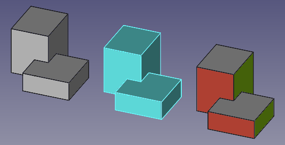
(1) An original object, (2) a Link with overriding material, and (3) a second Link with individual modified subelements.
Link Array
See also:
When a Link is created, by default its Element Count is {{Value|0}}, so only a single Link object will be visible in the tree view.
Given that Show Element is True by default, when Element Count is set to {{Value|1}} or more, automatically more Links will be created below the first one; each new Link can be placed in the desired position by changing its own Placement property.
In similar way, each element of the array can have its own appearance changed, either by the Override Material and Shape Material properties, or by using the Override colors menu on the entire array and then selecting individual faces; this is described in Overriding appearance.
<img alt="" src=https://raw.githubusercontent.com/FreeCAD/FreeCAD-documentation/master/wiki/images/Std_Link_tree_array_example.png ) 
(1) Original object, and (2, 3, 4) a Link array with three elements, each in a different position. The first Link has overridden material and transparent faces, the other two have custom face colors.
Once you are satisfied with the placement and properties of the Link elements in the array, you may change Show Element to False in order hide the individual Links in the tree view; this has the benefit of making the system more responsive, particularly if you have many objects in the document.
When creating this type of Link array, you must place each of the elements manually; however, if you would like to use specific patterns to place the copies, you may use the array tools of the Draft Workbench, like [ Draft OrthoArray, [ Draft PolarArray, and [ Draft CircularArray; these commands can create normal copies or Link copies depending on the options at creation time.
Visibility
When Show Element is True and individual elements are listed in the tree view in a Link Array, each Link can be shown or hidden by pressing the Space bar in the keyboard.
Another way to hide the individual elements is using the Override colors menu.
- Select the array, open the Override colors menu (right click).
- In the 3D view, pick any subelement from any Link in the array.
- Press Hide. An icon of an eye
 should appear, indicating that this element has been hidden from the 3D view. The object will temporarily show itself when the cursor hovers over the icon.
 - You can click OK to confirm the operation and close the dialog. The Link will remain hidden even if it is shown as visible in the tree view.

Element color dialog that is available when opening the context menu of a Link object in the tree view.
If you wish to restore the visibility of this array element, enter the dialog once more, pick the eye icon, then click on Remove to remove the hidden status, and click OK to confirm and close the dialog. The element will be visible in the 3D view again.
When the Link is for a [ Std Part or a [ Std Group, the Override colors menu works in similar way as with arrays; it allows controlling the face color, entire object color, and visibility of the objects in the group.


A Std Part containing three objects, and a Link to that Part; in the Link, (1) the first object is made invisible, (2) the second object has some subelements with different colors, (3) the entire third object has a different color and level of transparency.
Properties
An App Link (App::Link class) is derived from the basic App DocumentObject (App::DocumentObject class), therefore it has the latter\'s basic properties like Label and Label2.
The following are the specific properties available in the property editor. Hidden properties can be shown by using the Show all command in the context menu of the property editor.
Data
{{TitleProperty| Link}}
-
ColoredElements|LinkSubHidden|LockDynamic, Hidden: list of Link elements that have had their color overriden.
-
Element Count|IntegerConstraint|LockDynamic: Link element count. It defaults to {{Value|0}}. If it is {{Value|1}} or larger, the App Link will behave like an array, and will duplicate the same Linked Object many times. If Show Elements is
True, each element in the array will be displayed in the tree view, and each can have its own Placement modified. Each Link copy will have a name based on the Link\'s Name, augmented by_iN, whereNis a number starting from0. For example, with a singleLink, the copies will be namedLink_i0,Link_i1,Link_i2, etc. -
ElementList|LinkList|Immutable, Hidden, LockDynamic: the list of Link elements.
-
LinkClaimChild|Bool|LockDynamic: Claim the linked object as a child
-
LinkCopyOnChange|Enumeration|LockDynamic:
-
{{value|Disabled}}
    : disable the creation of a copy of the linked object, triggered by a change of any of its properties set as {{value|CopyOnChange}}.

-
    {{value|Enabled}}

    : enable a deep copy of the linked object if any of its properties marked as {{value|CopyOnChange}} are changed. After the deep copy is performed, there won\'t be any linkage between the original and the copied object. Therefore, changes in the original object won\'t be reflected in the copies.

-
    {{value|Owned}}

    : indicates that the linked object has been copied and is owned by the Link. This state is set automatically by the Link itself, a user would normally not do that. The link will try to sync any change of the original linked object back to the copy (Editor\'s note: the latter seems not to be implemented in FreeCAD main).

-
    {{value|Tracking}}

: same as {{value|Enabled}}, but additionally the copy will be automatically refreshed if the original source object changes.-
LinkCopyOnChangeGroup|Link|Hidden, LockDynamic: Linked to a internal group object for holding on change copies
-
LinkCopyOnChangeSource|XLink|Hidden, LockDynamic: The copy on change source object
-
LinkCopyOnChangeTouched|Bool|Hidden, LockDynamic: Indicating the copy on change source object has been changed
-
LinkExecute|String|LockDynamic: name of the execute function that will run for this particular Link object. It defaults to {{Value|'appLinkExecute'}}. Set it to {{Value|'None'}} to disable it.
-
Link Placement|Placement|Hidden, LockDynamic: it is an offset applied on top of the Placement of the Linked Object. This property is normally hidden but appears if Link Transform is set to
True; in this case, Placement now becomes hidden. -
Link Transform|Bool: it defaults to
False, in which case the Link will override the Linked Object\'s own placement. If it is set toTrue, the Link will be placed in the same position as the Linked Object, and its placement will be relative to the Linked Object\'s placement. This can also be achieved with [ Std LinkMakeRelative. -
Linked Object|XLink: it indicates the source object of the App Link; this can be an entire object, or a subelement of it (vertex, edge, or face).
-
Placement|Placement: the placement of the Link in absolute coordinates.
-
PlacementList|PlacementList|LockDynamic: The placement for each Link element
-
Scale|Float: it defaults to {{Value|1.0}}. It is a factor for uniform scaling in each direction
X,Y, andZ. For example, a cube of {{Value|2 mm}} x {{Value|2 mm}} x {{Value|2 mm}}, that is scaled by {{Value|2.0}}, will result in a shape with dimensions {{Value|4 mm}} x {{Value|4 mm}} x {{Value|4 mm}}. -
Scale List|VectorList: the scale factor for each Link element.
-
Scale Vector|Vector|Hidden: the scale factor for each component
(X, Y, Z)for all Link elements when Element Count is {{Value|1}} or larger. If Scale is other than {{Value|1.0}}, this same value will be used in the three components. -
Show Element|Bool: it defaults to
True, in which case the tree view will show the individual Link copies, as long as Element Count is {{Value|1}} or larger. -
_ChildCache|LinkList|NoPersist, ReadOnly, Hidden: TBD
-
_LinkOwner|Integer|Hidden, Output: TBD
-
_LinkTouched|Bool|NoPersist, Hidden: TBD
{{TitleProperty|Base}}
- Proxy|PythonObject|Hidden: a custom class associated with this object. This only exists for the Python version. See Scripting.
The App Link object will additionally show the properties of the original Linked Object, so the property editor may have groups of properties like {{TitleProperty|Attachment}}, {{TitleProperty|Box}}, {{TitleProperty|Draft}}, etc.
View
{{TitleProperty| Link}}
-
Draw Style|Enumeration: it defaults to {{Value|None}}; it can be {{value|Solid}}, {{value|Dashed}}, {{value|Dotted}}, {{value|Dashdot}}; defines the style of the edges in the 3D view.
-
Line Width|FloatConstraint: a float that determines the width in pixels of the edges in the 3D view. It defaults to {{value|2.0}}.
-
Override Material|Bool: it defaults to
False; if set toTrueit will override the Linked Object\'s material, and it will display the colors defined in Shape Material. -
Point Size|FloatConstraint: similar to Line Width, defines the size of the vertices.
-
Selectable|Bool: if it is
True, the object can be picked with the pointer in the 3D view. Otherwise, the object cannot be selected until this option is set toTrue. -
Shape Material|Material: this property includes sub-properties that describe the appearance of the object.
-
Diffuse Color
    , it defaults to  light blue .

-
    **Ambient Color**

    , it defaults to  dark gray .

-
    **Specular Color**

    , it defaults to  black .

-
    **Emissive Color**

    , it defaults to  black .

-
    **Shininess**

    , it defaults to {{Value|0.2}}

-
    **Transparency**

    , it defaults to {{Value|0.0}}.
{{TitleProperty|Base}}
-
Child View Provider|PersistentObject|Hidden:
-
Material List|MaterialList|Hidden: (read-only) if individual materials have been added, they will be listed here.
-
Override Color List|ColorList|Hidden: (read-only) if the individual faces or edges of the link have been overridden they will be listed here.
-
Override Material List|BoolList|Hidden: (read-only) if the individual materials of the link have been overridden they will be listed here.
{{TitleProperty|Display Options}}
-
Display Mode|Enumeration: {{Value|'Link'}} or {{Value|'ChildView'}}.
-
Show In Tree|Bool: see the information in App FeaturePython.
-
Visibility|Bool: see the information in App FeaturePython.
{{TitleProperty|Selection}}
-
On Top When Selected|Enumeration: see the information in App FeaturePython.
-
Selection Style|Enumeration: see the information in App FeaturePython.
It will additionally show the view properties of the original Linked Object.
Inheritance
An App Link is formally an instance of the class App::Link, whose parent is the basic App DocumentObject (App::DocumentObject class). It is a very low level object, which can be used with most other document objects.

Simplified diagram of the relationships between the core objects in the program. The `App::Link object is a core component of the system, it does not depend on any workbench, but it can be used with most objects created in all workbenches.`
Scripting
See also:
FreeCAD Scripting Basics, and scripted objects.
See Part Feature for the general information.
An App Link is created with the
import FreeCAD as App

doc = App.newDocument()
bod1 = App.ActiveDocument.addObject("Part::Box", "Box")
bod2 = App.ActiveDocument.addObject("Part::Cylinder", "Cylinder")
bod1.Placement.Base = App.Vector(10, 0, 0)
bod2.Placement.Base = App.Vector(0, 10, 0)

obj1 = App.ActiveDocument.addObject("App::Link", "Link")
obj2 = App.ActiveDocument.addObject("App::Link", "Link")

obj1.LinkedObject = bod1
obj2.setLink(bod2)
obj1.Placement.Base = App.Vector(-10, -10, 0)
obj2.Placement.Base = App.Vector(10, -10, 0)
obj1.ViewObject.OverrideMaterial = True
App.ActiveDocument.recompute()
The basic App::Link doesn\'t have a Proxy object so it can\'t be fully used for sub-classing.
Therefore, for Python subclassing, you should create the App::LinkPython object.
import FreeCAD as App

doc = App.newDocument()
obj = App.ActiveDocument.addObject("App::LinkPython", "Link")
obj.Label = "Custom label"
Further reading
If you want to skip the historical details, go to the user-oriented introduction to links.
The App Link object was introduced after 2 years of development and prototyping. This component was thought and developed almost single-handedly by user realthunder. The motivations and design implementations behind this project are described in his GitHub page, Link. In order to accomplish this feature, several core changes to FreeCAD were made; these were also extensively documented in Core-Changes.
The App Link project started after the redesign of the PartDesign Workbench was complete in v0.17. The history of App Link can be traced to some essential forum threads:
- Why an object can only be inside one App::Part? (March 2017)
- Introducing App::Link/XLink (March 2017)
- Links (May 2017)
- Realthunder Link implementation: Architecture discussion (June 2017)
- PR #876: Link, stage one, context aware selection (July 2017)
- Preview: Link, stage two, API groundwork (July 2017)
- Assembly3 preview (December 2017)
- Merging of my Link branch (June 2018)
Finally, the pull request and merge happened:
- App::Link: the big merge, old thread (July 2019), pull request #2350 (the BIG merge), LinkMerge branch.
- App::Link: the big merge, main thread (July 2019)
- A simple path description of Link, 019, Link stage, Asm3, merge? (August 2019)
- PR#2559: expose link and navigation actions, an introduction to the Link feature in 0.19 (September 2019).
Other miscellaneous \"links\" about Link include:
- Dynamic linked object - A pattern with Link and assemblies that aims to reduce duplication of assembly related logic such as orientation, positioning, or number of instances.
{{Std Base navi}}
⏵ documentation index > Std LinkMake
This page is retrieved from https://github.com/FreeCAD/FreeCAD-documentation/blob/main/wiki/Std_LinkMake.md