GuiCommand: Name: Part Wedge MenuLocation: Part , Part_Primitives , Wedge Workbenches: Part_Workbench, OpenSCAD_Workbench SeeAlso: Part_Primitives
Part Wedge
Description
A  Part Wedge is a parametric solid that can be created with the
  Part Primitives command. It has four to six planar faces. It is defined by virtual front and rear main planes on which a rectangular face (the default), a single straight edge or a single vertex is created. These base shapes define the four quadrilateral or triangular faces that connect them. The resulting solid is only a true wedge if one of the base shapes is a rectangular face and the other a straight edge. In the coordinate system defined by its Placement property, the virtual front and rear main planes of the wedge are plane-parallel to XZ plane, and the edges of the base shapes are parallel to the X or Z axis. All its coordinates are relative to that coordinate system.

Usage
See Part Primitives.
Example
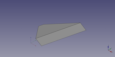
A Part Wedge object created with the scripting example below is shown here.
Notes
- The values of the coordinates of the wedge must be such that a valid solid can be create. This means that the front and rear base shapes can both be single edges, but not if they are parallel. And if one of the base shapes is a vertex the other shape must be a rectangular face.
Properties
See also: Property editor.
A Part Wedge object is derived from a Part Feature object and inherits all its properties. It also has the following additional properties:
Data
{{TitleProperty|Attachment}}
The object has the same attachment properties as a Part Part2DObject.
{{TitleProperty|Wedge}}
-
Xmin|Distance: The lowest X coordinate of the front face of the wedge. The default is {{Value|0mm}}.
-
Ymin|Distance: The Y coordinate of the front face of the wedge. The default is {{Value|0mm}}.
-
Zmin|Distance: The lowest Z coordinate of the front face of the wedge. The default is {{Value|0mm}}.
-
X2min|Distance: The lowest X coordinate of the rear face of the wedge. The default is {{Value|2mm}}.
-
Z2min|Distance: The lowest Z coordinate of the rear face of the wedge. The default is {{Value|2mm}}.
-
Xmax|Distance: The highest X coordinate of the front face of the wedge. The default is {{Value|10mm}}.
-
Ymax|Distance: The Y coordinate of the rear face of the wedge. The default is {{Value|10mm}}.
-
Zmax|Distance: The highest Z coordinate of the front face of the wedge. The default is {{Value|10mm}}.
-
X2max|Distance: The highest X coordinate of the rear face of the wedge. The default is {{Value|8mm}}.
-
Z2max|Distance: The highest Z coordinate of the rear face of the wedge. The default is {{Value|8mm}}.
Scripting
See also: Autogenerated API documentation, Part scripting and FreeCAD Scripting Basics.
A Part Wedge can be created with the {{Incode|addObject()}} method of the document:
wedge = FreeCAD.ActiveDocument.addObject("Part::Wedge", "myWedge")- Where {{Incode|"myWedge"}} is the name for the object.
- The function returns the newly created object.
Example:
import FreeCAD as App

doc = App.activeDocument()

wedge = doc.addObject("Part::Wedge", "myWedge")
wedge.Xmin = 1
wedge.Ymin = 2
wedge.Zmin = 3
wedge.X2min = 4
wedge.Z2min = 6
wedge.Xmax = 15
wedge.Ymax = 20
wedge.Zmax = 55
wedge.X2max = 10
wedge.Z2max = 12
wedge.Placement = App.Placement(App.Vector(1, 2, 3), App.Rotation(75, 60, 30))

doc.recompute()
{{Part_Tools_navi}}
⏵ documentation index > Part > Part Wedge
This page is retrieved from https://github.com/FreeCAD/FreeCAD-documentation/blob/main/wiki/Part_Wedge.md