GuiCommand:
Name: Draft Rectangle
MenuLocation: Drafting , Rectangle
2D Drafting , Rectangle
Workbenches: Draft_Workbench, BIM_Workbench
Shortcut: R E
Version: 0.7
Draft Rectangle
Description
The  Draft Rectangle command creates a rectangle on the current working plane from two points.
The corners of a Draft Rectangle can be filleted (rounded) or chamfered by changing its Fillet Radius or Chamfer Size respectively. It is also possible to subdivide a Draft Rectangle by changing its Columns and/or Rows property.
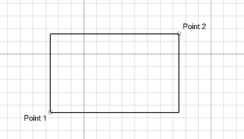 *Rectangle defined by two points*
Usage
See also: Draft Tray, Draft Snap and Draft Constrain.
- There are several ways to invoke the command:
- The Rectangle task panel opens. See Options for more information.
- Pick the first point in the 3D view, or type coordinates and press the
 Enter point button.
 - Pick the second point in the 3D view, or type coordinates and press the Enter point button. This point must not be constrained to the X, Y or Z axis.
Options
The single character keyboard shortcuts available in the task panel can be changed. See Draft Preferences. The shortcuts mentioned here are the default shortcuts (for version 1.0).
- To manually enter coordinates enter the X, Y and Z component, and press Enter after each. Or you can press the Enter point button when you have the desired values. It is advisable to move the pointer out of the 3D view before entering coordinates.
- Press R or click the Relative checkbox to toggle relative mode. If relative mode is on, the coordinates of the second point are relative to the first point, else they are relative to the coordinate system origin.
- Press G or click the Global checkbox to toggle global mode. If global mode is on, coordinates are relative to the global coordinate system, else they are relative to the working plane coordinate system.
- Press F or click the Filled checkbox to toggle filled mode. If filled mode is on, the created rectangle will have Make Face set to
Trueand will have a filled face. - Press N or click the Continue checkbox to toggle continue mode. If continue mode is on, the command will restart after finishing, allowing you to continue creating rectangles.
- Press S to switch Draft snapping on or off.
- Press Esc or the Close button to abort the command.
Notes
- A Draft Rectangle can be edited with the Draft Edit command.
Preferences
See also: Preferences Editor and Draft Preferences.
- If the Edit → Preferences... → Draft → General → Create Part primitives if possible option is checked, the command will create a Part Plane instead of a Draft Rectangle.
Properties
See also: Property editor.
A Draft Rectangle object is derived from a Part Part2DObject and inherits all its properties. It also has the following additional properties:
Data
{{TitleProperty|Draft}}
-
Area|Area: (read-only) specifies the area of the face of the rectangle. The value will be {{value|0.0}} if Make Face if
False. -
Chamfer Size|Length: specifies the length of the chamfers at the corners of the rectangle.
-
Columns|Integer: specifies the number of equal-sized columns in which the rectangle is divided.
-
Fillet Radius|Length: specifies the radius of the fillets at the corners of the rectangle.
-
Height|Distance: specifies the height of the rectangle.
-
Length|Distance: specifies the length of the rectangle.
-
Make Face|Bool: specifies if the rectangle makes a face or not. If it is
Truea face is created, otherwise only the perimeter is considered part of the object. -
Rows|Integer: specifies the number of equal-sized rows in which the rectangle is divided.
View
{{TitleProperty|Draft}}
-
Pattern|Enumeration: specifies the Draft Pattern with which to fill the face of the rectangle. This property only works if Make Face is
Trueand if Display Mode is {{value|Flat Lines}}. -
Pattern Size|Float: specifies the size of the Draft Pattern.
-
Texture Image|File: specifies the path of the image file to be mapped onto the face of the rectangle. Blanking this property will remove the image. The rectangle should have the same proportions as the image to avoid distortions.
Scripting
See also: Autogenerated API documentation and FreeCAD Scripting Basics.
To create a Draft Rectangle use the make_rectangle method ((v0.19) ) of the Draft module. This method replaces the deprecated makeRectangle method.
rectangle = make_rectangle(length, height, placement=None, face=None, support=None)- Creates a
rectangleobject withlengthin the X direction andheightin the Y direction, with units in millimeters. - If
placementisNonethe rectangle is created at the origin and the length will be parallel to the X axis. - If
faceisTrue, the rectangle will make a face, that is, it will appear filled.
Example:
import FreeCAD as App
import Draft

doc = App.newDocument()

rectangle1 = Draft.make_rectangle(4000, 1000)
rectangle2 = Draft.make_rectangle(1000, 4000)

zaxis = App.Vector(0, 0, 1)
p3 = App.Vector(1000, 1000, 0)
place3 = App.Placement(p3, App.Rotation(zaxis, 45))

rectangle3 = Draft.make_rectangle(3500, 250, placement=place3)

doc.recompute()
⏵ documentation index > Draft > Draft Rectangle
This page is retrieved from https://github.com/FreeCAD/FreeCAD-documentation/blob/main/wiki/Draft_Rectangle.md