GuiCommand:
Name: Draft CubicBezCurve
MenuLocation: Drafting , Bézier tools , Cubic Bézier curve
2D Drafting , Cubic Bézier curve
Workbenches: Draft_Workbench, BIM_Workbench
Version: 0.19
SeeAlso: Draft_BezCurve, Draft_BSpline
Draft CubicBezCurve
Description
The  Draft CubicBezCurve command creates a Bézier curve of the third degree (four points required).
The Bézier Curve is one of the most commonly used curves in computer graphics. This command allows you to create a continuous spline made up of several 3rd-degree Bézier segments, in a way that is similar to the Bézier tool in Inkscape. A general Bézier curve of any degree can be created with the Draft BezCurve command.
The Draft BezCurve and the Draft CubicBezCurve commands use control points to define the position and curvature of the spline. The Draft BSpline command, on the other hand, specifies the exact points through which the curve will pass.
 *Spline consisting of three cubic Bézier segments. The first segment is defined by four points. Subsequent segments reuse two points from the previous segment and therefore require only two additional points.*
Usage
See also: Draft Tray, Draft Snap and Draft Constrain.
- There are several ways to invoke the command:
- Press the Cubic Bézier curve button.
- Draft: Select the Drafting → Bézier tools → Cubic Bézier curve option from the menu.
- BIM: Select the 2D Drafting → Cubic Bézier curve option from the menu.
- Press the
- The Cubic Bézier curve task panel opens. See Options for more information.
- It is not possible the enter points via the task panel.
- For the following Mouse Navigation Models a keyboard key must to be held down:
- If you are using OpenInventor Navigation the Ctrl key must be held down throughout the command.
- If you are using Gesture Navigation the Alt key must be held down for each click-hold-release sequence, but is also possible to keep this key held down throughout the command.
- Pick the first point in the 3D view and hold the mouse button (1), this is the first endpoint.
- Drag the pointer to another point in the 3D view and release the mouse button (2), this is the first control point.
- Move the pointer to another point in the 3D view, pick this point and hold the mouse button (3), this is the second endpoint.
- Move the pointer to another point in the 3D view to adjust the final curvature of the segment and release the mouse button (4), this is the second control point.
- You now have one Bézier curve of the 3rd degree.
- Optionally repeat the process of clicking and holding (5), and dragging and releasing (6) to add more segments.
- Each subsequent segment will use the second endpoint and second control point of the previous segment as its first endpoint and first control point respectively.
- Press Esc or the Close button to finish the command.
Options
See Draft BezCurve.
Notes
- A Draft CubicBezCurve can be edited with the Draft Edit command.
Properties
See Draft BezCurve.
Scripting
See also: Autogenerated API documentation and FreeCAD Scripting Basics.
See Draft BezCurve for general information. A cubic Bézier is created by passing the option degree=3 to makeBezCurve().
For each cubic Bézier segment four points must be used, of which the two extreme points indicate where the spline passes through, and the two intermediate points are control points.
- If only 3 points are given, it creates a quadratic Bézier instead, with only one control point.
- If only 2 points are given, it creates a linear Bézier, that is, a straight line.
- If 5 points are given, the first 4 create a cubic Bézier segment; the 4th and the 5th points are used to create a straight line.
- If 6 points are given, the first 4 create a cubic Bézier segment; the 4th and the other two points are used to create a quadratic Bézier segment.
- If 7 points are given, the first 4 create a cubic Bézier segment; the 4th and the other three points are used to create a second cubic Bézier segment.
- In general, the last point in a group of four is shared with the following three points maximum to create another Bézier segment.
- To have smooth curves, with no straight segments, the number of points should be
3n + 1or3n, wherenis the number of segments, for n >= 1.
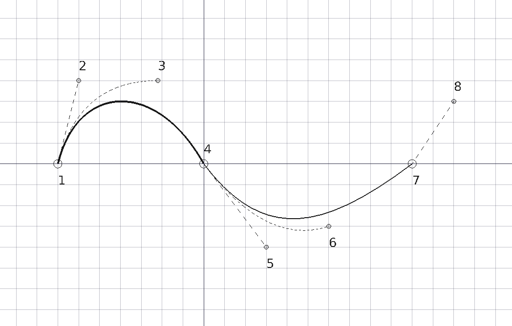
Examples of Bézier curves produced by using 2, 3, 4, 5, 6, 7, and 8 points. The solid lines indicate cubic Bézier segments; the other lines are quadratic or linear.
Example:
import FreeCAD as App
import Draft

doc = App.newDocument()

p1 = App.Vector(-3500, 0, 0)
p2 = App.Vector(-3000, 2000, 0)
p3 = App.Vector(-1100, 2000, 0)
p4 = App.Vector(0, 0, 0)

p5 = App.Vector(1500, -2000, 0)
p6 = App.Vector(3000, -1500, 0)
p7 = App.Vector(5000, 0, 0)
p8 = App.Vector(6000, 1500, 0)
rot = App.Rotation()

c1 = Draft.make_circle(100, placement=App.Placement(p1, rot), face=False)
c1.Label = "B1_E1"
c2 = Draft.make_circle(50, placement=App.Placement(p2, rot), face=True)
c2.Label = "B1_c1"
c3 = Draft.make_circle(50, placement=App.Placement(p3, rot), face=True)
c3.Label = "B1_c2"
c4 = Draft.make_circle(100, placement=App.Placement(p4, rot), face=False)
c4.Label = "B1_E2"
c5 = Draft.make_circle(50, placement=App.Placement(p5, rot), face=True)
c5.Label = "B2_c3"
c6 = Draft.make_circle(50, placement=App.Placement(p6, rot), face=True)
c6.Label = "B2_c4"
c7 = Draft.make_circle(100, placement=App.Placement(p7, rot), face=False)
c7.Label = "B2_E3"
c8 = Draft.make_circle(50, placement=App.Placement(p8, rot), face=True)
c8.Label = "B3_c5"

doc.recompute()

B1 = Draft.make_bezcurve([p1, p2], degree=3)
B1.Label = "B_lin"
B1.ViewObject.DrawStyle = "Dashed"

B2 = Draft.make_bezcurve([p1, p2, p3], degree=3)
B2.Label = "B_quad"
B2.ViewObject.DrawStyle = "Dotted"

B3 = Draft.make_bezcurve([p1, p2, p3, p4], degree=3)
B3.Label = "B_cub"
B3.ViewObject.LineWidth = 4

B4 = Draft.make_bezcurve([p1, p2, p3, p4, p5], degree=3)
B4.Label = "B_cub+lin"
B4.ViewObject.DrawStyle = "Dashed"

B5 = Draft.make_bezcurve([p1, p2, p3, p4, p5, p6], degree=3)
B5.Label = "B_cub+quad"
B5.ViewObject.DrawStyle = "Dotted"

B6 = Draft.make_bezcurve([p1, p2, p3, p4, p5, p6, p7], degree=3)
B6.Label = "B_cub+cub"
B6.ViewObject.LineWidth = 2

B7 = Draft.make_bezcurve([p1, p2, p3, p4, p5, p6, p7, p8], degree=3)
B7.Label = "B_cub+cub+lin"
B7.ViewObject.DrawStyle = "Dashed"

doc.recompute()
⏵ documentation index > Draft > Draft CubicBezCurve
This page is retrieved from https://github.com/FreeCAD/FreeCAD-documentation/blob/main/wiki/Draft_CubicBezCurve.md