GuiCommand: Name: CAM Pocket Shape MenuLocation: CAM , Pocket Shape Workbenches: CAM_Workbench
CAM Pocket Shape
Description
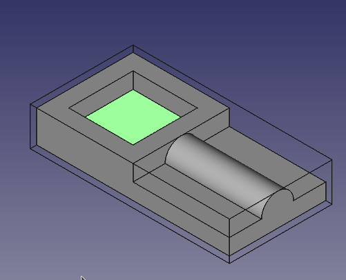
The  Pocket Shape tool creates a pocketing operation from selected bottom faces, or walls, of one or more pockets of the jobs base object.
The CAM Pocket Shape object is made to be part of a  CAM Job.
Usage
- Select the bottom or the wall(s) of a pocket. While it is usually easier to select the bottom, the walls have to be selected when a pocket goes through all.
- There are several ways to invoke the command:
- Press the CAM Pocket Shape button.
- Select the CAM → Pocket Shape option from the menu.
- Press the
- Adjust the desired properties.
Properties
Note: Not all of these Properties are available in the Task Window Editor. Some are only accessible in the Data tab of the Properties View panel for this Operation.
{{TitleProperty|Base}}
Note: It is suggested that you do not edit the Placement property of path operations. Rather, move or rotate the CAM Job model as needed.
-
Placement: Overall placement[position and rotation] of the object - with respect to the origin (or origin of parent object container)
-
Angle
    : Angle in degrees applied to rotation of the object around Axis property value

-
    **Axis**

    : Axis (one or multiple) around which to rotate the object, set in sub-properties: X, Y, Z

    -
        **X**

        : X axis value

    -
        **Y**

        : Y axis value

    -
        **Z**

        : Z axis value

-
    **Position**

    : Position of the object, set in sub-properties: X, Y, Z - with respect to the origin (or origin of parent object container)

    -
        **X**

        : X distance value

    -
        **Y**

        : Y distance value

    -
        **Z**

: Z distance value- Label: User-provided name of the object (UTF-8)
{{TitleProperty|Depth}}
-
Clearance Height: The height needed to clear clamps and obstructions
-
Final Depth: Final Depth of Tool- lowest value in Z
-
Finish Depth: Maximum material removed on final pass. The height (thickness) of the last cutting level - set for a better finish.
-
Safe Height: The height above which Rapid motions are allowed. (Rapid safety height between locations)
-
Start Depth: Starting depth of Tool - first cut depth in Z
-
Step Down: Incremental step down of Tool during operation
 *Visual reference for Depth properties (settings)*
{{TitleProperty|Extension}}
-
Extension Corners: When enabled connected extension edges are combined to wires.
-
Extension Length Default: Default length of extensions.
{{TitleProperty|Face}}
- Offset Pattern: Clearing pattern to use. (Select in which manner the horizontal movements should be done.)
{{TitleProperty|Path}}
-
Active: Make False, to prevent operation from generating code
-
Comment: An optional comment for this Operation
-
User Label: User assigned label
-
Tool Controller: Defines the Tool controller used in the Operation
{{TitleProperty|Pocket}}
-
Cut Mode: Specifies a CW or CCW move for the cut
-
Extra Offset: Extra offset to apply to the operation. Direction is operation dependent. (Extra value to stay away from final profile good for roughing toolpath)
-
Keep Tool Down: Attempts to avoid unnecessary retractions.
-
Min Travel: Use 3D Sorting of Path (when multiple base geometries used).
-
Start At: Start pocketing at center or boundary.
-
Step Over: Select the horizontal step over (Percent of tool diameter: 100% = tool diameter).
-
Use Outline: Uses the outline of the base geometry.
-
Zig Zag Angle: Angle of the zigzag pattern. (Select the path angle relative to X axis.)
{{TitleProperty|Rotation}}
-
Attempt Inverse Angle: Automatically attempt Inverse Angle if initial rotation is incorrect.
-
Enable Rotation: Enable rotation to gain access to pockets or areas not normal to Z axis.
-
Inverse Angle: Inverse the angle of the rotation. Example: change a rotation from -22.5 to 22.5 degrees.
-
Reverse Direction: Reverse orientation of Operation by 180 degrees.
{{TitleProperty|Start Point}}
-
Start Point: The start point of this path.
-
Use Start Point: Make True, if manually specifying a Start Point, then enter Start Points in the property data Start Points field.
Tasks Window Editor Layout
Descriptions for the settings are provided in the Properties list above.
This section is simply a layout map of the settings in the window editor for the Operation.
Base Geometry
- Add: Adds selected element(s) which should be the base(s) for the path(s)
- Delete: Delete the selected item(s) in the Base Geometry list
- Clear: Clear all items in the Base Geometry list
Extensions
-
Show All: If selected, all potential extensions are visualized. Enabled extensions in purple, disabled extensions in yellow.
-
Extension Corners
-
Extension Length Default
-
Enable
-
Disable
-
Clear
Depths
-
Start Depth
-
Final Depth
-
Step Down
Heights
-
Safe Height
-
Clearance Height
Operation
-
Tool Controller
-
Cut Mode
-
Pattern(Offset Pattern)
-
Angle(Zig Zag Angle)
-
Step Over Percent(Step Over)
-
Pass Extension: The distance the facing operation will extend beyond the boundary shape (base geometry)
Scripting
See also:
#Place code example here.{{CAM_Tools_navi}}
⏵ documentation index > CAM > CAM Pocket Shape
This page is retrieved from https://github.com/FreeCAD/FreeCAD-documentation/blob/main/wiki/CAM_Pocket_Shape.md