| Topic |
|---|
| Assembly3, a simple mechanism |
| Level |
| Basic knowledge of Assembly3 tools is helpful |
| Time to complete |
| 30 minutes |
| Authors |
| FBXL5 |
| FreeCAD version |
| 0.20 and later |
| Example files |
| None |
| See also |
| None |
Введение
This tutorial is about how to set up a simple mechanism, mainly with the tools from the external ![]() Assembly3 Workbench.
Assembly3 Workbench.
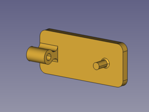
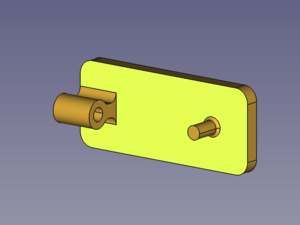
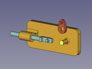
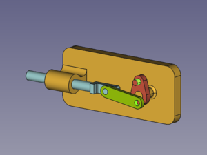
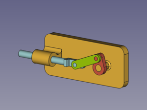
The kinematic assembly we will create consists of four parts: a Base, a Slider, a Crank, and a connecting Rod. They are connected with four joints.

Assembled parts: Base (amber), Slider (light blue), Crank (red), connecting Rod (green)
Assembly
Parts
The Base is an object with two main geometries, a hole and a pin. Both are cylindrical. The rest of the shape is not relevant for this tutorial unless it causes clashes. The same goes for the other parts.
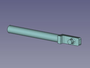
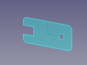
The Slider consists of a shaft with a pin on one end. Both are cylindrical.
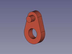
The Crank has a hole and a pin. Again both are cylindrical.
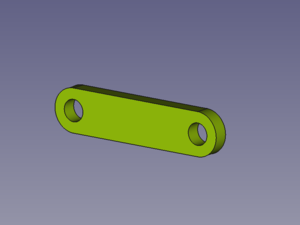
The Rod has two cylindrical holes.
Joints
Locked Base
To keep the assembly at the desired position, the base part should be locked.
- (If the
 Lock mover command is activated, motion tools are deactivated as long as a locked part is selected.)
- Select one face of the Base.
- Press the button
 Create "Locked" constraint to keep the Base in place permanently.
![]()
Selected face → Resulting Element
Then all four parts are connected with four joints. The kinematic chain starts at the base.
Base-to-Slider joint
The Base-to-Slider joint is a cylindrical joint. It enables the Slider to slide along and spin around the Base hole's Z axis while keeping both elements' Z axes aligned (colinear).
The matching constraint is the "AxialAlignment" constraint. It works with elements that represent cylindrical geometry such as cylindrical faces, circular faces and circular edges.
- Select the cylindrical faces of the Base hole and the Slider shaft.
- Press the button
 Create "AxialAlignment" constraint.
 - Optionally relabel the created elements (edit their ДанныеLabel property).
![]()
Selected faces → Aligned objects
Base-to-Crank joint
The Base-to-Crank joint is a hinge joint. It enables the Crank to spin around the Base pin's Z axis while keeping both elements' Z axes aligned (colinear) and the offset between their XY planes constant.
The matching constraint is the "PlaneCoincident" constraint. It works with elements that represent planar geometry such as circular faces and circular edges (in this case).
- Select the circular face or the outer circular edge of the Base pin, and the outer circular edge of the Crank hole.
- Press the button
 Create "PlaneCoincident" constraint.
 - Optionally relabel the created elements.
![]()
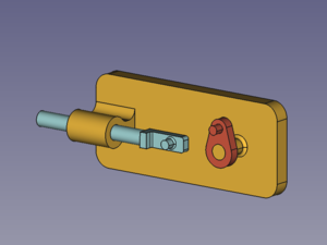
Selected face and edge → Aligned objects
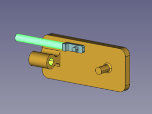
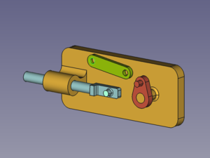
Slider-to-Rod joint
The Slider-to-Rod joint is a hinge joint. It enables the Rod to spin around the Slider pin's Z axis while keeping both elements' Z axes aligned (colinear) and the offset between their XY planes constant.
The matching constraint is the "PlaneCoincident" constraint (see above).
- Select the circular face or the outer circular edge of the Slider pin, and the outer circular edge of the Rod hole.
- Press the button Create "PlaneCoincident" constraint.
- Optionally relabel the created elements.
![]()
Selected face and edge → Aligned objects
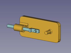
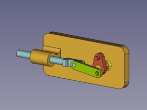
Crank-to-Rod joint
The Crank-to-Rod joint is a cylindrical joint. It enables the Rod to spin around and slide along the Crank pin's Z axis while keeping both elements' Z axes aligned (colinear). But only spinning will be possible as the sliding movement is restricted through the combination of the Base-to-Crank joint and the Slider-to-Rod joint.
The matching constraint is the "AxialAlignment" constraint (see above).
- Select the cylindrical faces of the Crank pin and the Rod hole.
- Press the button Create "AxialAlignment" constraint.
- Optionally relabel the created elements.
![]()
Selected faces → Aligned objects
Redundant Constraints
When the Base is fixed and all four joints are constrained two messages appear in the Report view:
- A warning (orange): "...redundant constraints".
- A simple message (black): "...dof remaining: 0".
This combination of messages occurs when parts of an assembly are over-constrained but the solver is still able to find a valid solution. But what causes the redundacy?
It is the Z direction of the pins. If we take a look at the Slider pin for example we will notice that the Z axis of its element object is constrained parallel to the Base pin's Z axis through the assembly chain Base-Crank-Rod-Slider. This means that the Slider pin is prevented from rotating around its X and Y axes.
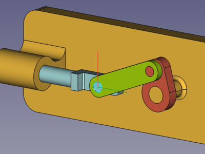
On the other hand the rotation around the X axis (red) is already prevented by the Base-to-Crank joint; and so the corresponding degree of freedom (dof) is constrained twice (= redundant) and causes the warning.
- To avoid this redundancy an auxilliary object and corresponding constraints could be inserted, but that is for some other tutorial.
- To avoid double constraining the offset between base and Rod, different constraints were used, with only one of them fixing the motion along the Z axis.
Actuator
Now it is still a static assembly. To turn it into a kinematic assembly one constraint has to be used as an actuator. To use the "PlaneCoincident" constraint of the Base-to-Crank joint as an actuator, we need to control the angle between Base pin and Crank. This can be done by setting the property ДанныеLock Angle to true. And for later use the label is marked with the suffix .Driver.
The ДанныеAngle property can now be used to spin the Crank.
Controller
To have a dialog window to change property values without typing and with automatic recomputation would be nice.
Have a look at the Kinematic Controller tutorial.
Эта страница получена от https://wiki.freecad.org/Tutorial_KinematicAssembly