|
|
| Menu location |
|---|
| Rocket → Fin |
| Workbenches |
| Rocket Workbench |
| Default shortcut |
| None |
| Introduced in version |
| 0.19 |
| See also |
| None |
Description
Fins are used to aerodynamically control the direction of flight.
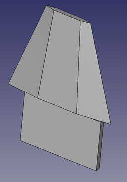
A Tapered fin with TTW tab
Usage
- There are several ways to invoke the command:
- Set options and press OK.
Options
Fin Type
The general shape of the fin.
- Trapezoid.
This fin type is used for almost all 4 sided fins. The root remains fixed, but the leading and trailing edges can have variable amounts of sweep. The chord length of the root and tip are set independently.

Trapezoid fin type
- Elliptical.
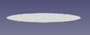
A generalized rounded shape. Circular fins are a special case where the height is 1/2 of the root chord.

Elliptical fin type
- Custom.
Most fins will fit into one of the standard shapes. In cases where they don't it's possible to create a custom shape using a sketch.
The sketch must be created first. The fin root is drawn along the positive X axis. With the sketch selected in the model tree, selecting the Fin icon will create the custom fin. The fin profile can be changed at this time.
There is no way to associate a custom fin with a sketch within the dialog after it's been created, so it is important to create the sketch first. It can be selected from the Properties view. Updating the sketch will update the fin.
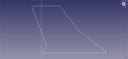
Sketch used to create a custom fin shape
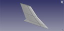
The custom fin created from the sketch
Cross Section
The cross sectional shape of a fin can greatly affect its performance at different speeds, as well as the looks of the rocket. A variety of fin cross sections have been implemented. Fins are created by lofting the root cross section to the tip cross section, so not all combinations of Root Cross Section and Tip Cross Section will produce useful fins.
- Square. Both the leading and trailing edges are squared.

Square Cross Section
- Round. The leading and trailing edges are rounded.
Round cross section
- Airfoil. Uses the NACA symmetrical airfoil shape NACA airfoil with maximum thickness at 30% of the chord.
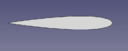
Airfoil cross section
- Wedge. The trailing edge of the fin is square, converging to a point at the leading edge.
Wedge cross section
- Diamond. The diamond shape starts from a point at the leading edge, straight out to the maximum thickness at a point determined by Length 1, and back to a point at the trailing edge.
![]()
Diamond cross section
- Leading Edge (LE) Taper. The leading edge is tapered to a point as determined by Length 1.
![]()
Leading edge taper cross section
- Trailing Edge (TE) Taper. The trailing edge is tapered to a point as determined by Length 1.
![]()
Trailing edge taper cross section
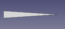
- Taper. The leading edge is tapered to a point as determined by Length 1, and the trailing edge is tapered to a point as determined by Length 2.
![]()
Taper cross section
Through the Wall (TTW) Tabs
Through the Wall fins add structural strength by extending though the outer body tube to an inner body tube such as a motor mount. Instead of attaching just to the outside of the outer body tube, it can be attached at multiple points. As such, the height of the tab would be the distance from the outer diameter of the inner body tube to the outer diameter of the outer body tube. Other parameters would vary depending on requirements.
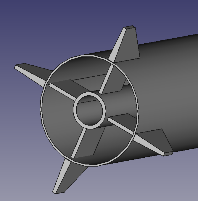
4 TTW fins attached to a central motor mount inside the outer body tube
Properties
Fin
- DataFin Type: Defines the shape of the fin.
- DataHeight: The fin height.
- DataProfile: The sketch associated with the custom fin type.
- DataRoot Chord: The distance between the fin leading and trailing edges at the root
- DataRoot Cross Section: The cross section shape of the fin at the root, see Options
- DataRoot Length 1: Usage depends on the Fin Root Cross Section and will apply to a taper length or similar, see Options
- DataRoot Length 2: Usage depends on the Fin Root Cross Section and will apply to a taper length or similar when multiple values are required, see Options
- DataRoot Per Cent: Expresses the Fin Root Length 1 and Fin Root Length 2 properties as a percentage of the Fin Root Chord
- DataRoot Thickness: Maximum thickness at the root of the fin
- DataSweep Angle: The angle of the front of the fin, with a vertical front being 0 degrees. This may be negative. Setting this value will cause the Sweep Length to be adjusted.
- DataSweep Length: The distance from the front of the fin root to the front of the fin tip along the x axis. This may be negative. Setting this value will cause the Sweep Angle to be adjusted.
- DataTip Chord: The distance between the fin leading and trailing edges at the tip
- DataTip Cross Section: The cross section shape of the fin at the tip, see Options
- DataTip Length 1: Usage depends on the Fin Tip Cross Section and will apply to a taper length or similar, see Options
- DataTip Length 2: Usage depends on the Fin Tip Cross Section and will apply to a taper length or similar when multiple values are required, see Options
- DataTip Per Cent: Expresses the Fin Tip Length 1 and Fin Tip Length 2 properties as a percentage of the Fin Tip Chord
- DataTip Thickness: Maximum thickness at the tip of the fin
- DataTtw: True when a tab for Through the Wall fins is required, see Options
- DataTtw Height: Height of the TTW tab
- DataTtw Length: Length of the TTW tab
- DataTtw Offset: Distance from the front of the fin to the front of the TTW tab
- DataTtw Thickness: Thickness of the TTW tab
Rocket Component
These parameters are provided for information and have no effect on the design of the component.
- DataDescription: Description of the component
- DataManufacturer: Manufacturer when known
- DataMaterial: Material when known
- DataPart Number: Manufacturer part number
Tutorials and Learning
Rocket Workbench Fins Tutorial on YouTube
This page is retrieved from https://wiki.freecad.org/Rocket_Fin