Overview
Descriere
Placement reprezintă modul cum FreeCAD specifică poziția și atitudinea(orientarea) unui obiect în spațiu. Plasamentul poate fi specificat în mai multe forme și manipulată prin scripting, Proprietățile panel sau dialogul Placement (Edit menu).
Accesarea Atributelor Plasament
Atributele de plasare ale unui obiect pot fi accesate și modificate în trei moduri:
Accessing the Placement Attribute
An object's Placement attributes can be accessed and modified in 3 ways:

Placement in property editor

Scripting Placement as y/p/r and Matrix and its API
Placement task panel
Forms of Placement
Forme de Placement
Plasarea este stocată intern ca poziție și o rotație (axa de rotație și unghiul transformat într-un quaternion [1]). Deși există mai multe formulare pentru specificarea unei rotații, de exemplu cu un centru de rotație, aceasta este utilizată numai pentru a afecta calculul rotației și nu este stocată pentru operații ulterioare. În mod similar, dacă se specifică o axă de rotație de (1,1,1), aceasta poate fi normalizată atunci când este stocată în quaternion și apare ca (0,58, 0,58, 0,58) atunci când navighează obiectul mai târziu.
Angle, Axis and Position
Unghi, Axă și Poziție
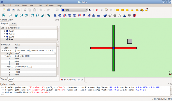
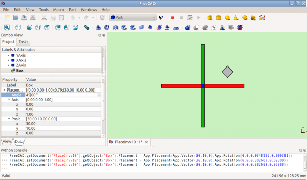
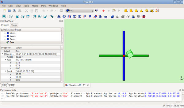
Placement = [Angle, Axis, Position]
Prima formă de Plasare stabilește locația unui obiect în spațiu cu o Poziție și descrie orientarea acestuia ca o singură rotire în jurul unei axe. Angle = r este un scalar care indică mărimea rotației a obiectului față de o Axă. Este introdus în grade, dar este stocat intern ca radiani.
Angle = r is a scalar indicating the amount of rotation of the object about Axis. Entered as degrees, but stored internally as radians.
Axis = (ax,ay,az) este un vector care descria o axă de rotație (See Note about axis of rotation). Examples are:
   (1,0,0)       ==> about X axis
   (0,1,0)       ==> about Y axis
   (0,0,1)       ==> about Z axis
   (0.71,0.71,0) ==> about the line y=x
(1,0,0) ==> about X axis
   (0,1,0)       ==> about Y axis
   (0,0,1)       ==> about Z axis
   (0.71,0.71,0) ==> about the line y=x
Rețineți că este de asemenea posibil să traduceți (mutați) un obiect de-a lungul acestei axe de rotație (mișcare axială) prin introducerea distanței pentru deplasare în caseta de declanșare axială și făcând clic pe butonul Aplicare axial. (O modalitate de a imagina mișcarea axială este să ne gândim la un avion cu o elice care se rotește - elicele se rotesc în jurul unei axe de rotație în timp ce avionul se mișcă de-a lungul aceleiași axe .) Valorile din vector pot fi considerate drept mărimea relativă a mișcării care va fi aplicată în acea direcție. De exemplu, în cazul y = x (0,71,0,71,0), valoarea din spinboxul axial se aplică în egală măsură direcțiilor X și Y, dar nu se produce nici o mișcare în direcția Z.
Position = (x,y,z) is a Vector describing the point from which the object's geometry will be calculated (in effect, a "local origin" for the object). Note that in scripts, Placement.Base is used to denote the Position component of a placement. The Property Editor calls this value "Position" and the Placement dialog calls it "Translation".
Position = (x,y,z) is a Vector describing the point from which the object's geometry will be calculated (in effect, a "local origin" for the object). Note that in scripts, Placement.Base is used to denote the Position component of a placement. The property editor calls this value Position and the Placement task panel calls it Translation.
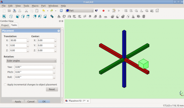
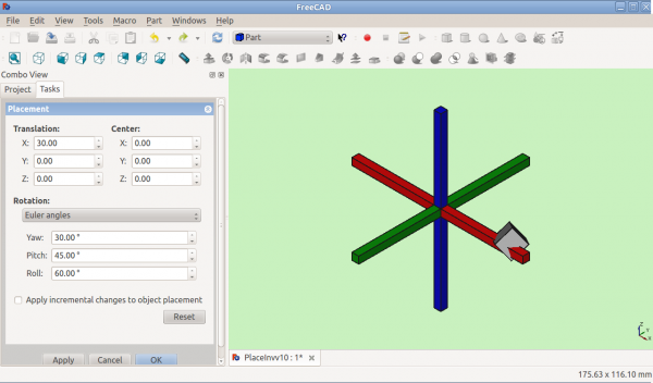
Position and Yaw, Pitch and Roll

Placement task panel: Euler angles ![]() selected
selected
Placement = [Position, Yaw-Pitch-Roll]
The second form of Placement fixes an object's location in space with a Position (as in the first form), but describes it's orientation using Yaw, Pitch and Roll angles (Yaw, Pitch, Roll). These angles are sometimes referred to as Euler angles or Tait-Bryan angles (Euler angles). Yaw, Pitch and Roll are common aviation terms for a body's orientation (or attitude).
Position = (x,y,z) is a Vector describing the point from which the object's geometry will be calculated (in effect, a "local origin" for the object).
Yaw-Pitch-Roll = (y,p,r) is a tuple that specifies the attitude of the object. Values for y,p,r specify degrees of rotation about each of the z,y,x axis (see note).
>>> App.getDocument("Sans_nom").Cylinder.Placement=App.Placement(App.Vector(0,0,0), App.Rotation(10,20,30), App.Vector(0,0,0))
>>> App.ActiveDocument.Cylinder.Placement = App.Placement(App.Vector(0,0,0), App.Rotation(10,20,30), App.Vector(0,0,0))
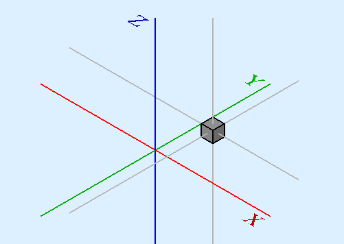
App.Rotation(10,20,30) = Euler Angle
Yaw = 10 degrees (Z)
Pitch = 20 degrees (Y)
Roll = 30 degrees (X)
Yaw is the rotation about the Z axis, that is to say a rotation from left to right.
(The yaw angle is the Psi ψ).
Pitch is rotation about the Y axis, that is to say nose-up and nose-down.
(The Pitch angle is the Phi φ).
Roll is rotation about the X axis, that is to say wing up and down.
(The Roll angle is the Thêta θ).
Matrix
Matrix
Placement = Matrix
The third form of Placement describes the object's position and orientation with a 4x4 affine transformation matrix (Affine Transformation).
Matrix =
((r11,r12,r13,t1),
   (r21,r22,r23,t2),
   (r31,r32,r33,t3),
   (0,0,0,1)) , with rij specifying rotation and ti specifying translation.
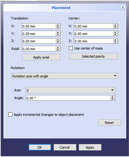
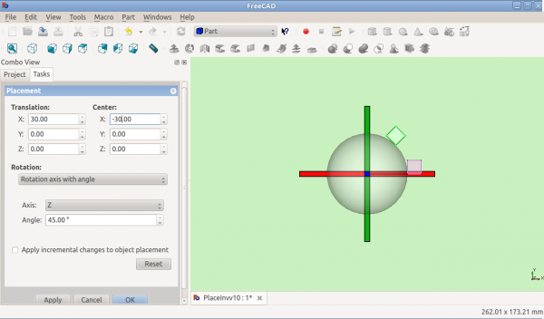
The Placement Dialog
The Placement Dialog
Dialogul de plasare este invocat din meniul Edit. Este folosit pentru a roti/transla precis obiectele. Este de asemenea folosit atunci când trebuie să creăm o schiță pe un plan "nonstandard" sau să schimbăm orientarea unei schițe într-un nou plan.
The Translation section adjusts the object's location in space. The Center section adjusts the rotational axis to one that does not pass through the object's reference point. The Rotation section adjusts the rotational angle(s) and the method of specifying those angles.
- The Translation section adjusts the object's location in space.
- The Center section adjusts the rotational axis to one that does not pass through the object's reference point.
- The Rotation section adjusts the rotational angle(s) and the method of specifying those angles.
Deși elementele din fiecare secțiune se aplică în general scopului acestei secțiuni, unele elemente ale unei secțiuni pot afecta, de asemenea, elementele dintr-o altă secțiune. De exemplu, dacă dați clic pe butonul Puncte selectat în secțiunea Centrucu 2 puncte selectate în vizualizarea 3D, completați nu numai casetele de selectareCentru în mijlocul acestor două puncte selectate, dar creează, de asemenea, o axă personalizată de-a lungul liniei definite de aceste două puncte selectate în secțiunea Rotație. Într-un alt exemplu, plasați o valoare în caseta de declanșare Axial și faceți clic pe butonul Apply Axis din secțiunea Translatare muta obiectul de-a lungul axei definite în secțiunea Rotație.
The Apply incremental changes to object placement tick box is useful when translations/rotations are to be made relative the object's current position/attitude, rather than to the original position/attitude. Ticking this box resets the dialogue input fields to zero, but does not change the object's orientation or location. Subsequent entries do change the orientation/location, but are applied from the object's current position. Enabling this checkbox is also useful when using the Selected points button as it can sometimes prevent undesired placement changes.
The Apply incremental changes to object placement tick box is useful when translations/rotations are to be made relative the object's current position/attitude, rather than to the original position/attitude. Ticking this box resets the dialogue input fields to zero, but does not change the object's orientation or location. Subsequent entries do change the orientation/location, but are applied from the object's current position. Enabling this checkbox is also useful when using the Selected points button as it can sometimes prevent undesired placement changes.
PS: de la versiunea 0.17 se introduce un obiectnou tip Part, acest obiect are plasarea sa, iar obiectul Plasare creat în obiectul Parte este incrementat cu Plasarea parțială.introduced in 0.17 Pentru a obține Part Placement utilizați acest cod
To obtain the Part Placement use this code:
import Draft, Part
sel = FreeCADGui.Selection.getSelection()
print(sel[0].Placement)
print(sel[0].getGlobalPlacement())   # return the GlobalPlacement
print(sel[0].getParentGeoFeatureGroup()) # return the GeoFeatureGroup, ex:  Body or a Part.
print("____________________")
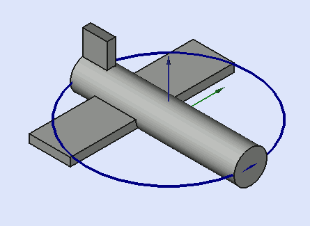
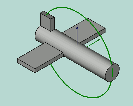
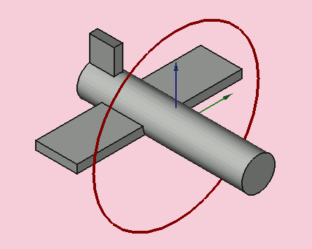
Butonul Selected Points se utilizează pentru a completa marcatorii dinCentru 'și (când sunt selectați 2 sau 3 puncte) coordonează casetele de selecție pentru a crea o axă de rotație personalizată secțiunea Rotație. Un punct poate fi un vârf, dar poate fi orice punct de-a lungul unei muchii sau a unei fețe. Când selectați o margine sau o față, este selectată întreaga margine sau față, dar FreeCAD își amintește și punctul de pe acea față sau margine pe care indicatorul mouse-ului a rulat atunci când marginea sau fața au fost selectate. Coordonatele acestui punct sunt folosite în caseta de dialog Destinație de plasare când faceți clic pe butonul Selected points . S-ar putea să vă gândiți că nu este o modalitate foarte precisă de a selecta un punct și că aveți dreptate, dar în multe cazuri este suficient ca punctul selectat să fie garantat pe marginea sau pe fața respectivă. În cazurile în care trebuie să desemnați în mod specific un punct de utilizat, trebuie să selectați un vârf. Dacă nu există nici un vârf în locația dorită, luați în considerare crearea unei imagini, de exemplu, într-o schiță temporară atașată la acea față sau margine, posibil utilizând un obiect Draft Workbench, cum ar fi linie sau punct etc.
Să analizăm mai întâi cazul simplu de selectare a unui punct. Fluxul de lucru este selectat mai întâi, apoi faceți clic pe butonul Puncte selectate. Coordonatele punctului selectat vor fi folosite pentru a popula cutiile de spin X, Y și Z din secțiunea Centru. Acum orice rotire făcută obiectului va fi referitoare la acest centru de rotație.
Acum, luați în considerare cazul selectării a 2 puncte. Veți selecta cele 2 puncte dorite, apoi faceți clic pe butonul Puncte selectate. Coordonatele punctului intermediar dintre cele două puncte selectate sunt plasate în casetele de derulare X, Y și Z din secțiunea Centru. De acum înainte, orice rotire efectuată asupra obiectului se referă la acest centru de rotație. Dar, pe lângă configurația secțiunii Centru, se adaugă de asemenea o axă personalizată (definită de utilizator) la elementul Axis al secțiunii Rotation. (Notă: Dacă ați fost în modul de rotire Euler, modul este rotit cu un mod axial și noua axă personalizată este selectată ca axă de rotație curentă.) Acum, orice rotație efectuată utilizând noua axă personalizată este această axă. de rotație. Ca bonus, distanța este măsurată între cele două puncte selectate și această informație este dată în ecranul Raport. (Notă: Țineți apăsată tasta Shift în timp ce faceți clic pe butonul Select Points 'pentru a copia măsurarea distanței în clipboard.) Introducerea acestei distanțe din meniul drop-down axial din secțiunea Translatare , apoi apăsarea butonului Aplicare Axă vă permite să mutați (mutați) obiectul astfel încât primul punct selectat ocupă acum coordonatele ocupate de al doilea punct selectat (momentan a fost selectat butonul Select Points ).
Luați în considerare acum cazul de selectare a 3 puncte. Ați selecta cele 3 puncte dorite, apoi faceți clic pe butonul Selectat puncte. Coordonatele primului punct selectat (ordinea de selecție este foarte importantă aici) sunt plasate în casetele de selecție X, Y și Z ale secțiunii Centru. Deoarece 3 puncte definesc un plan, FreeCAD poate profita de acesta și poate folosi aceste 3 puncte pentru a crea o nouă axă de rotație personalizată (definită de utilizator) care este normală (perpendiculară) cu planul respectiv. Ca și în cazul a două puncte selectate, distanța dintre puncte este de asemenea afișată în vizualizarea Raport, dar de această dată este distanța dintre punctele 2 și 3 selectate. (Notă: Țineți apăsată tasta Shift în timp ce dați clic pe butonul Selected points button -- Shift + Clickpentru a copia măsurarea unghiului în clipboard.) În plus, unghiul dintre al doilea și al treilea punct sunt, de asemenea, măsurate și afișate în vizualizarea raportului. Prin introducerea acestui unghi în zona de selectare a unghiurilor Rotation , putem roti obiectul foarte precis, astfel încât al doilea punct selectat să fie aliniat coordonatele ocupate de al treilea punct selectat. (Notă: poate doriți să măriți numărul de cifre utilizate în meniul Editare -> Preferințe -> General -> Unități -> Număr zecimale zecimale (dacă doriți mai multă precizie).)
Examples
Exemple
Rotația față de o singură axă:
Rotation with offset centre point:
Rotation with offset centre point:

Rotation using Euler angles:
Rotation using Euler angles:
Placement.Base vs Shape Definition
Placement.Base vs Shape Definition
Placement is not the only way to position a shape in space. Note the Python console in this image:

2 Shapes with the Same Placement
Both cubes have the same value for Placement, but are in different locations! This is because the 2 shapes are defined by different vertices (curves in more complex shapes). For the 2 shapes in the above illustration:
>>> ev = App.ActiveDocument.Extrude.Shape.Vertexes
 >>> for v in ev: print(v.X,",",v.Y,",",v.Z)
 ...
 0.0,0.0,0.0
 0.0,0.0,10.0
 10.0,0.0,0.0
 10.0,0.0,10.0
 10.0,10.0,0.0
 10.0,10.0,10.0
 0.0,10.0,0.0
 0.0,10.0,10.0
 >>> e1v = App.ActiveDocument.Extrude001.Shape.Vertexes
 >>> for v in e1v: print(v.X,",",v.Y,",",v.Z)
 ...
 20.0,30.0,0.0
 20.0,30.0,10.0
 20.0,20.0,0.0
 20.0,20.0,10.0
 30.0,20.0,0.0
 30.0,20.0,10.0
 30.0,30.0,0.0
 30.0,30.0,10.0
 >>>
The Vertices (or Vectors) that define the shape use the Placement.Base attribute as their origin. So if you want to move a shape 10 units along the X axis, you could add 10 to the X coordinates of all the Vertices or you could set Placement.Base to (10,0,0).
Using "Center" to Control Axis of Rotation
>>> ev = App.ActiveDocument.Extrude.Shape.Vertexes
 >>> for v in ev: print v.X,",",v.Y,",",v.Z
 ...
 30.0,30.0,0.0
 30.0,30.0,10.0
 40.0,30.0,0.0
 40.0,30.0,10.0
 40.0,40.0,0.0
 40.0,40.0,10.0
 30.0,40.0,0.0
 30.0,40.0,10.0
 >>> e1v = App.ActiveDocument.Extrude001.Shape.Vertexes
 >>> for v in e1v: print v.X,",",v.Y,",",v.Z
 ...
 0.0,10.0,0.0
 0.0,10.0,10.0
 10.0,10.0,0.0
 10.0,10.0,10.0
 10.0,0.0,0.0
 10.0,0.0,10.0
 0.0,0.0,0.0
 0.0,0.0,10.0
 >>>
The Vertices (or Vectors) that define the shape use the Placement.Base attribute as their origin. So if you want to move a shape 10 units along the X axis, you could add 10 to the X coordinates of all the Vertices or you could set Placement.Base to (10,0,0).
Using "Center" to Control Axis of Rotation
By default, the axis of rotation isn't really the x/y/z axis. It is a line parallel to the selected axis, but passing through the reference point (Placement.Base) of the object to be rotated. This can be changed by using the Center fields in the Placement dialog or, in scripts, by using the Center parameter of the FreeCAD.Placement constructor.
For example, suppose we have a box (below) positioned at (20,20,10).
We wish to spin the box around it's own vertical centre line (ie local Z), while keeping it the same position. We can easily achieve this by specifying a Center value equal to the coordinates of the box's central point (25,25,15).

In a script, we would do:
We wish to spin the box around it's own vertical centre line (ie local Z), while keeping it the same position. We can easily achieve this by specifying a Center value equal to the coordinates of the box's central point (25,25,15).
In a script, we would do:
import FreeCAD
obj = App.ActiveDocument.Box                       # our box
rot = FreeCAD.Rotation(FreeCAD.Vector(0,0,1),45)   # 45° about Z
#rot = FreeCAD.Rotation(FreeCAD.Vector(1,0,1),45)   # 45° about X and 45° about Z
#rot = FreeCAD.Rotation(10,20,30)                   # here example with Euler angle Yaw = 10 degrees (Z), Pitch = 20 degrees (Y), Roll = 30 degrees (X)
centre = FreeCAD.Vector(25,25,15)                  # central point of box
pos = obj.Placement.Base                           # position point of box
newplace = FreeCAD.Placement(pos,rot,centre)       # make a new Placement object
obj.Placement = newplace                           # spin the box
Same script with the file example RotateCoG2.fcstd (discussion on the forum)
import FreeCAD
obj = App.ActiveDocument.Extrude                    # our box
rot = FreeCAD.Rotation(FreeCAD.Vector(0,0,1),45)    # 45 about Z
#rot = FreeCAD.Rotation(FreeCAD.Vector(1,0,1),45)    # 45° about X and 45° about Z
#rot = FreeCAD.Rotation(10,20,30)                    # here example with Euler angle Yaw = 10 degrees (Z), Pitch = 20 degrees (Y), Roll = 30 degrees (X)
centre = FreeCAD.Vector(25,25,0)                    # "centre" of rotation (where local Z cuts XY)
pos = obj.Placement.Base                            # original placement of obj
newplace = FreeCAD.Placement(pos,rot,centre)        # make a new Placement object
obj.Placement = newplace                            # spin the box
Using Placement in expressions
In expressions it is possible to use the components of the placement for example to access the x-component of the object labeled "Cube":
<<Cube>>.Placement.Base.x
You can access the angle of the rotation by
<<Cube>>.Placement.Rotation.Angle
The axis of rotation can be accessed with
<<Cube>>.Placement.Rotation.Axis.x
<<Cube>>.Placement.Rotation.Axis.y
<<Cube>>.Placement.Rotation.Axis.z
where often one of these values is 1 while the others are 0.
You can also use the whole Placement in a single expression:
Right click on Placement property in the property editor, select "show hidden" then extra properties will show. If you then right click on Placement again the context menu will include Expression, select Expression then the Expression dialogue will open and whatever you type will go into the Placement property rather than its child properties.
To make the placement of "Sketch" equal to that of "Cylinder", you would enter in that way for Sketch the expression
<<Cube>>.Placement
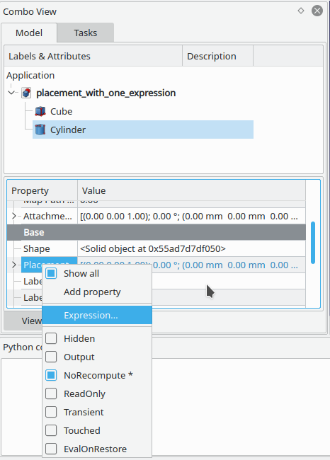
NOTE: It's also possible to create Placement objects in expressions. See the Expressions page for details.
Notes
Note
- Axa și unghiul pot fi exprimate și caquaternion.
- Punctul de referință al unui obiect variază în funcție de obiect. Câteva exemple pentru obiecte obișnuite:
| Object | Reference Point |
|---|---|
| Part.Box | left (minx), front (miny), bottom (minz) vertex |
| Part.Sphere | center of the sphere (ie centre of bounding box) |
| Part.Cylinder | center of the bottom face |
| Part.Cone | center of bottom face (or apex if bottom radius is 0) |
| Part.Torus | center of the torus |
| Features derived from Sketches | the Feature inherits the Position of the underlying Sketch.
Schițele încep întotdeauna cu poziția = (0,0,0). Această poziție corespunde originii din schiță. |
| Object | Reference Point |
|---|---|
| Part.Box | left (minx), front (miny), bottom (minz) vertex |
| Part.Sphere | center of the sphere (ie centre of bounding box) |
| Part.Cylinder | center of the bottom face |
| Part.Cone | center of bottom face (or apex if bottom radius is 0) |
| Part.Torus | center of the torus |
| Features derived from Sketches | the Feature inherits the Position of the underlying Sketch. Sketches always start with Position = (0,0,0). This position corresponds to the origin in the sketch. |
Suplimentar
- Acest tutorial: Aeroplane acoperă mecanica schimbării extensive a plasării unui obiect.
- O explicație pas-cu-pas a dialogului de plasare poate fi găsită aici Tasks_Placement.
Această pagină este preluată de la https://wiki.freecad.org/Placement